Product information(Main functions and features )
-
Lineup in Japan
-
FRENIC-VG
-
Product information
- Unit Type, Stack Type, Converters
- Comprehensive Line-up
- Improved Control Performance
- A Wide Range of Applications
- Easier Maintenance
- Easier Maintenance and Greater Reliability
- Adaptation to Environment and Safety
- How to expand the capacity range of the inverters (Stack Type)
- How to expand the capacity range of the PWM converters (Stack Type)
- Variation
- Applicable SiC Hybrid Module Model
- Specifications
- External Dimensions
-
Catalog Download
- Document Download
-
Product information
- FRENIC-MEGA (G2)
-
FRENIC-MEGA (G1)
-
Product information
- Best vector control for the general-purpose inverter in the class
- Accommodating various applications
- Wide model variation meeting the customer needs
- Supports for simple maintenance
- Network building
- Prolonged service life and improved life judgment function
- Consideration for environment
- Global compatibility
- Function Safety
- Variation
- Specifications
- External Dimensions
-
Catalog Download
- Document Download
-
Product information
-
FRENIC-Ace (E3)
- Product information
- Variation
- Specifications
- External Dimensions
-
Catalog Download
- Document Download
- FRENIC-Ace (E2)
- FRENIC-Mini
-
FRENIC-HVAC
- Product information
- Variation
- Specifications
- External Dimensions
-
Catalog Download
- Document Download
-
FRENIC-Eco
-
Product information
- Product appearance
- Exploded view of main body
- Keypad switches and functions
- Monitor display & key operation
- New energy-saving
- Long life design of inverters
- Simplified maintenance
- Optimum functions for HVAC
- Environment and panel design
- Operator-friendly features
- Network compatibility
- Global compatibility
- Variation
- Specifications
- External Dimensions
-
Catalog Download
- Document Download
-
Product information
-
FRENIC-Lift(LM1S)
- Product information
- Variation
- Specifications
- External Dimensions
-
Catalog Download
- Document Download
-
FRENIC-eRHR
- Product information
- Variation
- Specifications
- External Dimensions
-
Catalog Download
- Document Download
-
FRENIC-eRHC
- Product information
- Variation
- Specifications
- External Dimensions
-
Catalog Download
- Document Download
-
FRENIC-VG
-
Lineup in Europe
-
FRENIC-VG
-
Product information
- Unit Type, Stack Type, Converters
- Comprehensive Line-up
- Improved Control Performance
- A Wide Range of Applications
- Easier Maintenance
- Easier Maintenance and Greater Reliability
- Adaptation to Environment and Safety
- How to expand the capacity range of the inverters (Stack Type)
- How to expand the capacity range of the PWM converters (Stack Type)
- Variation
- Applicable SiC Hybrid Module Model
- Specifications
- External Dimensions
-
Catalog Download
- Document Download
-
Product information
- FRENIC-MEGA (G2)
-
FRENIC-MEGA (G1)
-
Product information
- Best vector control for the general-purpose inverter in the class
- Accommodating various applications
- Wide model variation meeting the customer needs
- Supports for simple maintenance
- Network building
- Prolonged service life and improved life judgment function
- Consideration for environment
- Global compatibility
- Function Safety
- Variation
- Specifications
- External Dimensions
-
Catalog Download
-
Product information
-
FRENIC-Ace (E3)
- Product information
- Variation
- Specifications
- External Dimensions
-
Catalog Download
- Document Download
- FRENIC-Ace (E2)
- FRENIC-Mini
- FVR-Micro
-
FRENIC-HVAC
- Product information
- Variation
- Specifications
- External Dimensions
-
Catalog Download
- Document Download
-
FRENIC-Eco
-
Product information
- Product appearance
- Exploded view of main body
- Keypad switches and functions
- Monitor display & key operation
- New energy-saving
- Long life design of inverters
- Simplified maintenance
- Optimum functions for HVAC
- Environment and panel design
- Operator-friendly features
- Network compatibility
- Global compatibility
- Variation
- Specifications
- External Dimensions
-
Catalog Download
- Document Download
-
Product information
- FRENIC-AQUA
-
FRENIC-Lift(LM1S)
- Product information
- Variation
- Specifications
- External Dimensions
-
Catalog Download
- Document Download
-
FRENIC-Lift(LM2A)
- Product information
- Variation
- Specifications
- External Dimensions
-
Catalog Download
- Document Download
-
FRENIC-eRHR
- Product information
- Variation
- Specifications
- External Dimensions
-
Catalog Download
- Document Download
-
FRENIC-eRHC
- Product information
- Variation
- Specifications
- External Dimensions
-
Catalog Download
- Document Download
-
FRENIC-VG
-
Lineup in North America
-
FRENIC-VG
-
Product information
- Unit Type, Stack Type, Converters
- Comprehensive Line-up
- Improved Control Performance
- A Wide Range of Applications
- Easier Maintenance
- Easier Maintenance and Greater Reliability
- Adaptation to Environment and Safety
- How to expand the capacity range of the inverters (Stack Type)
- How to expand the capacity range of the PWM converters (Stack Type)
- Variation
- Applicable SiC Hybrid Module Model
- Specifications
- External Dimensions
-
Catalog Download
- Document Download
-
Product information
- FRENIC-MEGA (G2)
-
FRENIC-MEGA (G1)
-
Product information
- Best vector control for the general-purpose inverter in the class
- Accommodating various applications
- Wide model variation meeting the customer needs
- Supports for simple maintenance
- Network building
- Prolonged service life and improved life judgment function
- Consideration for environment
- Global compatibility
- Function Safety
- Variation
- Specifications
- External Dimensions
-
Catalog Download
-
Product information
-
FRENIC-Ace (E3)
- Product information
- Variation
- Specifications
- External Dimensions
-
Catalog Download
- Document Download
- FRENIC-Ace (E2)
- FRENIC-Mini
-
FRENIC-HVAC
- Product information
- Variation
- Specifications
- External Dimensions
-
Catalog Download
- Document Download
-
FRENIC-Eco
-
Product information
- Product appearance
- Exploded view of main body
- Keypad switches and functions
- Monitor display & key operation
- New energy-saving
- Long life design of inverters
- Simplified maintenance
- Optimum functions for HVAC
- Environment and panel design
- Operator-friendly features
- Network compatibility
- Global compatibility
- Variation
- Specifications
- External Dimensions
-
Catalog Download
-
Product information
-
FRENIC-eRHR
- Product information
- Variation
- Specifications
- External Dimensions
-
Catalog Download
- Document Download
-
FRENIC-eRHC
- Product information
- Variation
- Specifications
- External Dimensions
-
Catalog Download
- Document Download
-
FRENIC-VG
-
Lineup in China
-
FRENIC-VG
-
Product information
- Unit Type, Stack Type, Converters
- Comprehensive Line-up
- Improved Control Performance
- A Wide Range of Applications
- Easier Maintenance
- Easier Maintenance and Greater Reliability
- Adaptation to Environment and Safety
- How to expand the capacity range of the inverters (Stack Type)
- How to expand the capacity range of the PWM converters (Stack Type)
- Variation
- Applicable SiC Hybrid Module Model
- Specifications
- External Dimensions
-
Catalog Download
- Document Download
-
Product information
- FRENIC-MEGA (G2)
-
FRENIC-MEGA (G1)
-
Product information
- Best vector control for the general-purpose inverter in the class
- Accommodating various applications
- Wide model variation meeting the customer needs
- Supports for simple maintenance
- Network building
- Prolonged service life and improved life judgment function
- Consideration for environment
- Global compatibility
- Function Safety
- Variation
- Specifications
- External Dimensions
-
Catalog Download
- Document Download
-
Product information
-
FRENIC-Ace (E3)
- Product information
- Variation
- Specifications
- External Dimensions
-
Catalog Download
- Document Download
- FRENIC-Ace (E2)
- FRENIC-Mini
- FVR-Micro
-
FRENIC VP
- Product information
- Variation
- Specifications
- External Dimensions
-
Catalog Download
-
For Europe
- For China
-
- Document Download
- FRENIC-Lift(LM1S)
- FRENIC-eRHR
-
FRENIC-eRHC
- Product information
- Variation
- Specifications
- External Dimensions
-
Catalog Download
- Document Download
-
FRENIC-VG
-
Lineup in Asia
-
FRENIC-VG
-
Product information
- Unit Type, Stack Type, Converters
- Comprehensive Line-up
- Improved Control Performance
- A Wide Range of Applications
- Easier Maintenance
- Easier Maintenance and Greater Reliability
- Adaptation to Environment and Safety
- How to expand the capacity range of the inverters (Stack Type)
- How to expand the capacity range of the PWM converters (Stack Type)
- Variation
- Applicable SiC Hybrid Module Model
- Specifications
- External Dimensions
-
Catalog Download
- Document Download
-
Product information
- FRENIC-MEGA (G2)
-
FRENIC-MEGA (G1)
-
Product information
- Best vector control for the general-purpose inverter in the class
- Accommodating various applications
- Wide model variation meeting the customer needs
- Supports for simple maintenance
- Network building
- Prolonged service life and improved life judgment function
- Consideration for environment
- Global compatibility
- Function Safety
- Variation
- Specifications
- External Dimensions
-
Catalog Download
- Document Download
-
Product information
-
FRENIC-Ace (E3)
- Product information
- Variation
- Specifications
- External Dimensions
-
Catalog Download
- Document Download
- FRENIC-Ace (E2)
- FRENIC-Mini
- FVR-Micro
-
FRENIC-HVAC
- Product information
- Variation
- Specifications
- External Dimensions
-
Catalog Download
- Document Download
-
FRENIC-Eco
-
Product information
- Product appearance
- Exploded view of main body
- Keypad switches and functions
- Monitor display & key operation
- New energy-saving
- Long life design of inverters
- Simplified maintenance
- Optimum functions for HVAC
- Environment and panel design
- Operator-friendly features
- Network compatibility
- Global compatibility
- Variation
- Specifications
- External Dimensions
-
Catalog Download
- Document Download
-
Product information
- FRENIC-AQUA
- FRENIC eHVAC
-
FRENIC-Lift(LM1S)
- Product information
- Variation
- Specifications
- External Dimensions
-
Catalog Download
- Document Download
-
FRENIC-eRHR
- Product information
- Variation
- Specifications
- External Dimensions
-
Catalog Download
- Document Download
-
FRENIC-eRHC
- Product information
- Variation
- Specifications
- External Dimensions
-
Catalog Download
- Document Download
-
FRENIC-VG
-
Lineup in Taiwan
-
FRENIC-VG
-
Product information
- Unit Type, Stack Type, Converters
- Comprehensive Line-up
- Improved Control Performance
- A Wide Range of Applications
- Easier Maintenance
- Easier Maintenance and Greater Reliability
- Adaptation to Environment and Safety
- How to expand the capacity range of the inverters (Stack Type)
- How to expand the capacity range of the PWM converters (Stack Type)
- Variation
- Applicable SiC Hybrid Module Model
- Specifications
- External Dimensions
-
Catalog Download
- Document Download
-
Product information
- FRENIC-MEGA (G2)
-
FRENIC-MEGA (G1)
-
Product information
- Best vector control for the general-purpose inverter in the class
- Accommodating various applications
- Wide model variation meeting the customer needs
- Supports for simple maintenance
- Network building
- Prolonged service life and improved life judgment function
- Consideration for environment
- Global compatibility
- Function Safety
- Variation
- Specifications
- External Dimensions
-
Catalog Download
- Document Download
-
Product information
-
FRENIC-Ace (E3)
- Product information
- Variation
- Specifications
- External Dimensions
-
Catalog Download
- Document Download
- FRENIC-Ace (E2)
-
FRENIC-Eco
-
Product information
- Product appearance
- Exploded view of main body
- Keypad switches and functions
- Monitor display & key operation
- New energy-saving
- Long life design of inverters
- Simplified maintenance
- Optimum functions for HVAC
- Environment and panel design
- Operator-friendly features
- Network compatibility
- Global compatibility
- Variation
- Specifications
- External Dimensions
-
Catalog Download
- Document Download
-
Product information
-
FRENIC-Lift(LM1S)
- Product information
- Variation
- Specifications
- External Dimensions
-
Catalog Download
- Document Download
-
FRENIC-eRHR
- Product information
- Variation
- Specifications
- External Dimensions
-
Catalog Download
- Document Download
-
FRENIC-eRHC
- Product information
- Variation
- Specifications
- External Dimensions
-
Catalog Download
- Document Download
-
FRENIC-VG
-
Lineup in Korea
-
FRENIC-VG
-
Product information
- Unit Type, Stack Type, Converters
- Comprehensive Line-up
- Improved Control Performance
- A Wide Range of Applications
- Easier Maintenance
- Easier Maintenance and Greater Reliability
- Adaptation to Environment and Safety
- How to expand the capacity range of the inverters (Stack Type)
- How to expand the capacity range of the PWM converters (Stack Type)
- Variation
- Applicable SiC Hybrid Module Model
- Specifications
- External Dimensions
-
Catalog Download
- Document Download
-
Product information
- FRENIC-MEGA (G2)
-
FRENIC-MEGA (G1)
-
Product information
- Best vector control for the general-purpose inverter in the class
- Accommodating various applications
- Wide model variation meeting the customer needs
- Supports for simple maintenance
- Network building
- Prolonged service life and improved life judgment function
- Consideration for environment
- Global compatibility
- Function Safety
- Variation
- Specifications
- External Dimensions
-
Catalog Download
- Document Download
-
Product information
-
FRENIC-Ace (E3)
- Product information
- Variation
- Specifications
- External Dimensions
-
Catalog Download
- Document Download
- FRENIC-Ace (E2)
- FRENIC-Mini
- FRENIC-Eco
-
FRENIC-Lift(LM1S)
- Product information
- Variation
- Specifications
- External Dimensions
-
Catalog Download
- Document Download
-
FRENIC-eRHR
- Product information
- Variation
- Specifications
- External Dimensions
-
Catalog Download
- Document Download
-
FRENIC-eRHC
- Product information
- Variation
- Specifications
- External Dimensions
-
Catalog Download
- Document Download
-
FRENIC-VG

-
The front cover does not have to be removed.
-
No RS-485 converter is needed.
-
Commercial cables can be used.
-
Internal data, time and date around the fault are recorded.
The real-time clock (clock function) is built-in as standard. -
Data are backed up by battery.
Trace data can be stored in the memory even while the power is off.
-
*
-
Battery: 30kW or more (built-in as standard), up to 22kW (available as option: OPK-BP)
-
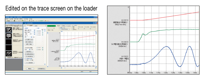
Trace waveform can be checked on the PC loader
Data editing and detailed data monitor analysis operations are much easier than with a conventional PC loader.
-
Function code setting
-
User-defined displays (customized displays), data explanation display for each code.
-
Trace function
-
Real-time trace: for long-term monitoring
Historical trace: for detailed data diagnosis for short periods
Trace back: for fault analysis (last three times)
-
*
-
The paid-for loader software (WPS-VG1-PCL) supports real-time tracing and historical tracing.
-
*
-
The paid-for loader software (WPS-VG1-STR) is contained in the CD-ROM provided with the product. (Can be downloaded from the Fuji website.)
-
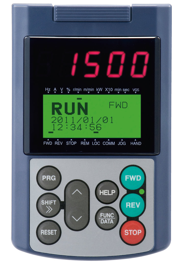
Wide 7-segment LED ensures easy view.
-
The back-light is incorporated in the LCD panel, which enables the easy inspection in the dark control panel.
-
Enhanced copy function
The function codes can be copied to other inverters easily. (Three patterns of function codes can be stored.) Copying data in advance reduces restoration time when problems occur, by replacing the Keypad when changing the inverter. -
Remote control operation is available.
The Keypad can be remotely operated by extending the cable length at the RJ-45 connector. -
JOG (jogging) operation can be executed using the Keypad.
-
The HELP key displays operation guidance.
-
Supported languages: English, Chinese, Korean (Hangul), Japanese
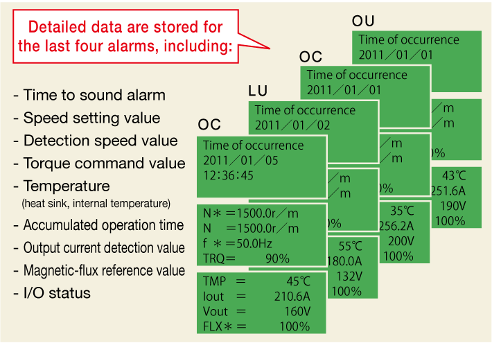
The number of alarm data to be stored has been increased from the conventional model. Thanks to the real-time clock function built-in as standard, the complete data of the latest and last 3 alarm occurences is stored: time, speed command, torque, current and others. This enables machine units to be checked for abnormalities.
⇒As for previous model, new alarm data overwrote and deleted existing alarm data.
This is solved with the new VG model.
Alarm severity (serious and minor) can be selected, eliminating the risk of critical facility stoppage due to a minor fault.
-
The PG interface circuit incorporated as standard detects disconnection of the power supply line as well as the PG signal line.
-
A mode was added that judges if it is a PG fault or a fault on the inverter side
Simulated output mode is provided at the PG pulse output terminal (FA and FB).
Operation can be checked by connecting this to the PG input terminal.
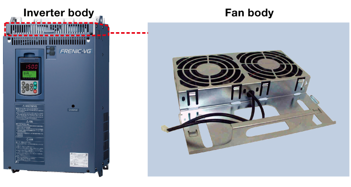
The cooling fan can easily be changed without removing the front cover and printed board.
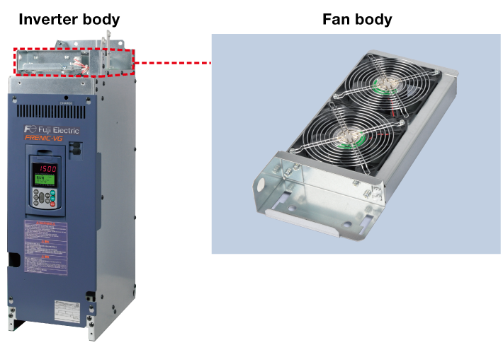
The cooling fan installed at the top can easily be changed without drawing the stacks.
However, for the 220kW or above inverter, remove the 2 connection bars from the DC side and change the cooling fan.
For the various consumable parts inside the inverter, their designed lives have been extended to 10 years.
This also extended the equipment maintenance cycles.
Life conditions
Unit type: ambient temperature 40 ℃, load factor 100% (HD spec.), 80% (MD spec., LD spec.)
Stack type: ambient temperature 30 ℃, load factor 100% (MD spec.), 80% (LD spec.)
-
*
-
The planned life is determined by calculation, and is not the guaranteed value.
-
Lifetime alarms can be checked rapidly on the Keypad and PC loader (optional).
-
Facility maintenance can be performed much easier thanks to lifetime alarms.
-
Customization of functions for test run and adjustment
(Individual items on the loader can be set to be displayed or not.) -
Simulated fault alarm issued by a special function on the Keypad
-
Monitor data hold function
-
Simulated operation mode
Simulated connection allows the inverter to be operated with internal parts in the same way as if they were connected to the motor, without actually being connected. -
The externally input I/O monitor and PG pulse states can be checked on the Keypad.
-
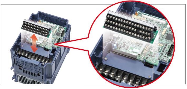
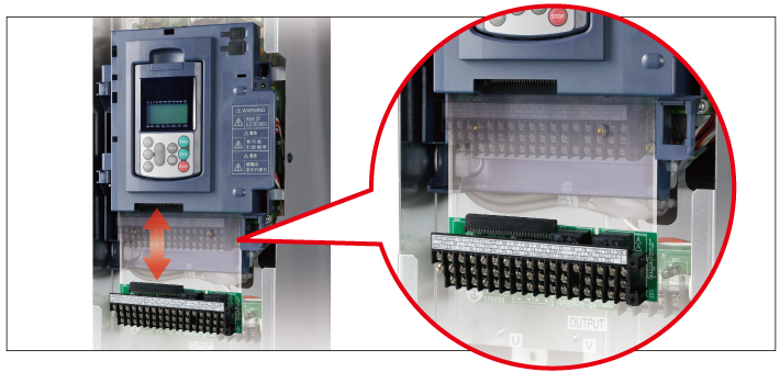
The terminal block can be connected to the inverter after control wiring work is completed. Wiring work is simplified.
-
Restoration time for updating equipment, problem occurrence, and inverter replacement has been drastically reduced. Just mount the wired terminal block board to the replaced inverter.
