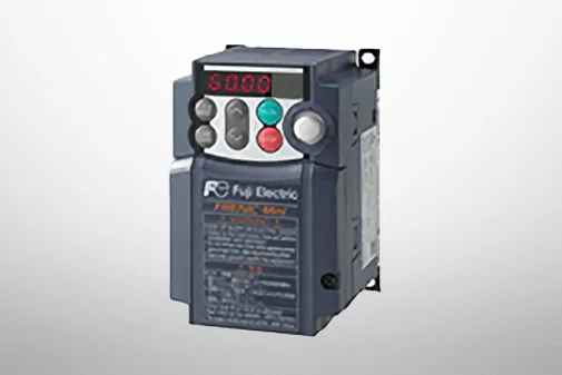
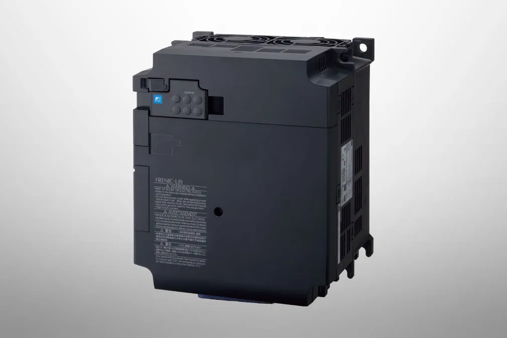
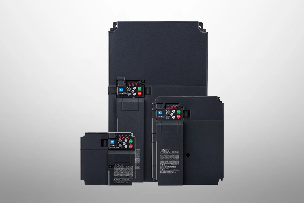
FRENIC-VG
Product information | A Wide Range of Applications
-
Ratings for intended use
-
A standard built-in brake circuit with expanded capacity range
-
High-speed, high-accuracy position control realized (servo function)
-
Control method
-
A wide range of options
-
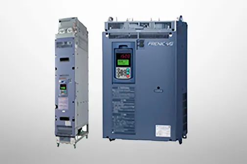
Dedicated design for panel installation (Stack Type)
-
690V Series Inverter Stack Capacity Expansion Through Adoption of SiC Hybrid Module (355 /400/450kW)
-
Also compatible with fan, pump applications
-
Support for ultrahigh-speed E-SX bus
The operation mode for the motor is selected according to motor load condition. Motors larger by one or two frames can be driven with medium load (MD) and light load (LD) use.
-
*1
-
This varies depending on motor specifications and power supply voltage.
-
*2
-
Carrier frequency becomes 2kHz.
Having a standard built-in brake circuit (with 200V 55kW or less and 400V 160KW or less), is useful when applying the inverter to the vertical transfer machine, which is frequently used under the regenerative load.
-
*
-
Unit type only
-
Built-in position control function as standard with pulse train input (A separate option (OPC-VG1-PG(PR)) is required for pulse train input.)
-
High-speed, high-accuracy position control is possible in combination with an E-SX bus and 17-bit high-resolution ABS encoder.
(The servo function is supported with a dedicated type.) (Soon to be supported)
Not only the induction motors but also the synchronous motors can be driven, and for the induction motors, you can select the most suitable control method according to your individual needs.
-
Providing options supporting various interfaces such as high-speed serial communications
-
Options can be used by just inserting them into the connectors inside the inverter. Up to four cards can be mounted.
(Combination with built-in control option: see page 48)
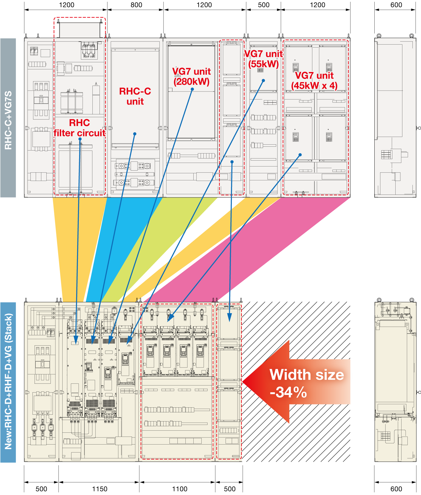
The use of a stack type designed specifically for panel installation has resulted in a reduced panel size compared with the conventional design. A 34% reduction in panel width has been achieved over the conventional design (example for crane system).
The dedicated design has also resulted in easier installation of products into the panel and easier replacement.
Fuji handles all processes from new development to production from the device level, and has realized an optimized SiC module design tailored to stacks. This has resulted in a 28% reduction in generated loss, facilitated a reduction in stack size, and allowed capacity to be expanded.
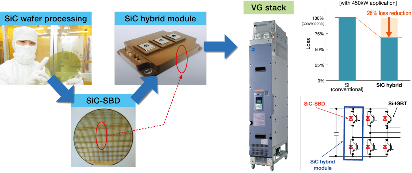
Through the adoption of an SiC hybrid module, generated loss has been reduced by 28%, and stack single unit capacity has been expanded to 450kW, while ensuring the same dimensions as stacks in the 250 to 315kW capacity range. (Stack width: 226.2 mm)
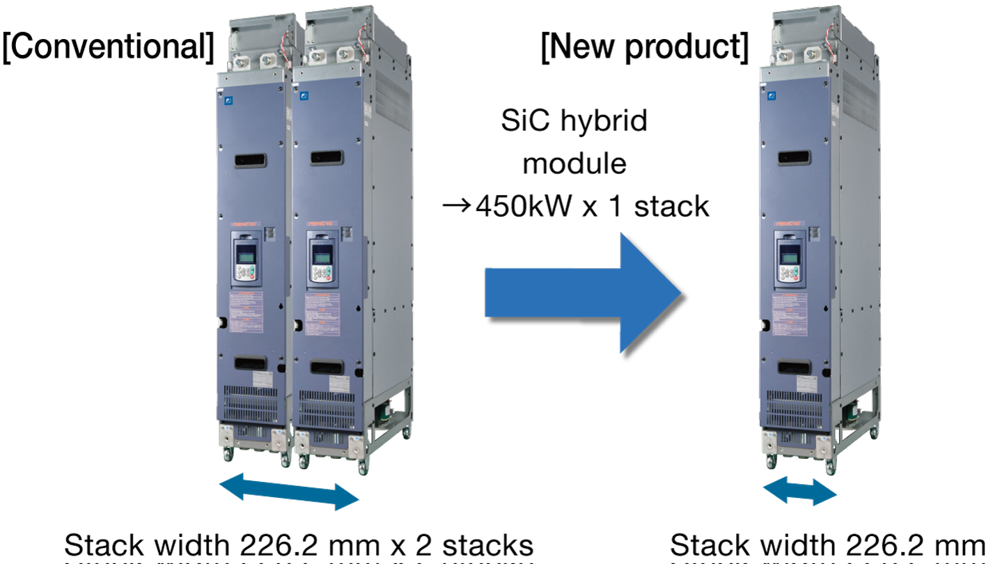
Dimensions and capacity comparison
Use of a "single" 450kW system configuration realized with SiC hybrid module application
-
Forced operation (Fire Mode)
The inverter protection function is ignored (retry), allowing operation to be continued. This allows fans and pumps to continue running as much as possible in times of emergency such as when there is a fire. -
Command loss detection function
If analog speed setting signals are interrupted, operation continues at the speed set with a function code. -
Low water quantity stop function
The inverter can be stopped if the pump discharge pressure rises and discharged water quantity drops. -
Broad capacity range
Capacity expansion is easy with parallel operation (direct parallel connection).

-
*1
-
The capacity expansion value indicates the nominal applied motor capacity.
-
*2
-
Capacity expansion applies to the direct parallel connection system. Up to three inverters can be connected in parallel.
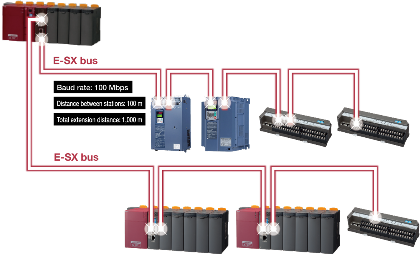
A PLC (MICREX-SX Series: SPH3000MM) and FRENIC-VG can be connected with the ultrahigh-speed communication E-SX bus.
With ultrahigh-speed commnucation, support is possible for even faster, more accurate devices.
