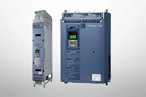
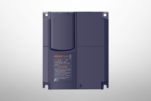
FRENIC-Lift (LM1S)
Standard Specifications | Basic Type


Basic type (Three-phase 200V)

-
Note1
-
Fuji’s 4-pole standard motor
-
Note2
-
Rated capacity is calculated by regarding the output rated voltage as 220V for three-phase 200V series.
-
Note3
-
Output voltage cannot exceed the power supply voltage.
-
Note4
-
It is a value in the condition of the carrier frequency 10kHz and the ambient temperature 45°C. Select the inverter capacity such that the square average current in cycle operation is 80% or less of the rated current of an inverter.
-
Note5
-
Voltage unbalance [%] = (Max. voltage [V] - Min. voltage [V])/ Three-phase average voltage [V] x 67 (IEC61800-3)
-
Note6
-
The power supply capacity is 500kVA (ten times the inverter capacity when the inverter capacity exceeds 50kVA), and the calculation value when connecting with the power supply of %X=5%.
-
Note7
-
Obtained when a DC Reactor is used.
-
Note8
-
An acceptable variation of the main power supply and the control power supply assistance input.
-
Note9
-
The admissible error of minimum resistance is ±5%.
-
Note10
-
-
Note11
-
The same AC power as the main power supply input is connected for the backup of the control circuit power source.
-
Note12
-
It is a value in the condition of the carrier frequency 10kHz and the ambient temperature 45°C. Use the inverter such that the square average current in battery
operation is 80% or less of the rated current of an inverter.
-
Note13
-
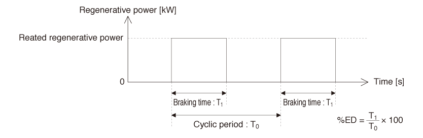
Braking time and duty cycle (%ED) are defined by cycle operation at the rated regenerative power as shown in the figure below.
-
Note14
-
The inverter that last 2 digits of a software version are from 50 to 99 corresponds to this standard.
-
Note15
-
When output exceeds this overload capacity at carrier frequency 16kHz, carrier frequency is reduced automatically. The reduced carrier frequency is maintained until
an inverter stops.
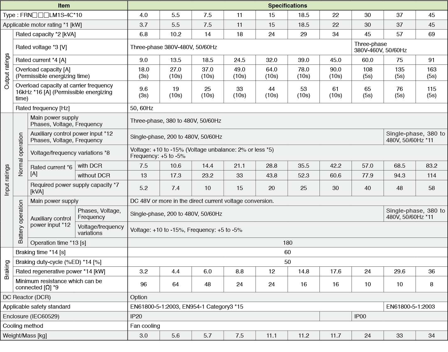
Basic type (Three-phase 400V)

-
Note1
-
Fuji’s 4-pole standard motor
-
Note2
-
Rated capacity is calculated by regarding the output rated voltage as 440V for three-phase 400V series.
-
Note3
-
Output voltage cannot exceed the power supply voltage.
-
Note4
-
It is a value in the condition of the carrier frequency 10kHz and the ambient temperature 45°C. Select the inverter capacity such that the square average current in cycle operation is 80% or less of the rated current of an inverter.
-
Note5
-
Voltage unbalance [%] = (Max. voltage [V] - Min. voltage [V])/ Three-phase average voltage [V] x 67 (IEC61800-3)
-
Note6
-
The power supply capacity is 500kVA (ten times the inverter capacity when the inverter capacity exceeds 50kVA), and the calculation value when connecting with the power supply of %X=5%.
-
Note7
-
Obtained when a DC Reactor is used.
-
Note8
-
An acceptable variation of the main power supply and the control power supply assistance input.
-
Note9
-
The admissible error of minimum resistance is ±5%.
-
Note10
-
-
Note11
-
It is necessary to change the power-supply voltage change connector on the power supply printed wiring board depend on the power-supply voltage.
-
Note12
-
30kW or less
The same AC power as the main power supply input is connected for the backup of the control circuit power source.
37kW or more The same AC power as the main power supply input is connected for the control circuit, the fan, and the contactor.
The inverter doesn’t operate if the power supply is not input to the auxiliary control power input. Please supply power.
-
Note13
-
It is a value in the condition of the carrier frequency 10kHz and the ambient temperature 45°C. Use the inverter such that the square average current in battery operation is 80% or less of the rated current of an inverter.
-
Note14
-
Braking time and duty cycle (%ED) are defined by cycle operation at the rated regenerative power as shown in the figure below.
-
Note15
-
The inverter that last 2 digits of a software version are from 50 to 99 corresponds to this standard.
-
Note16
-
When output exceeds this overload capacity at carrier frequency 16kHz, carrier frequency is reduced automatically. The reduced carrier frequency is maintained until an inverter stops.
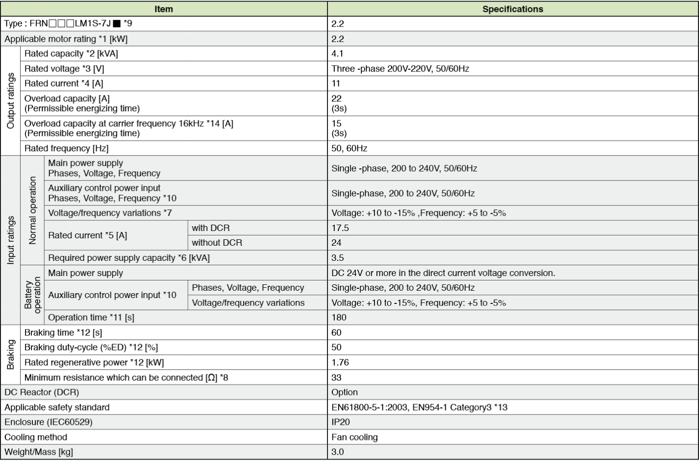
Basic type (Single-phase 200V)

-
Note1
-
Fuji’s 4-pole standard motor
-
Note2
-
Rated capacity is calculated by regarding the output rated voltage as 220V.
-
Note3
-
Output voltage cannot exceed the power supply voltage.
-
Note4
-
It is a value in the condition of the carrier frequency 10kHz and the ambient temperature 45°C. Select the inverter capacity such that the square average current in cycle operation is 80% or less of the rated current of an inverter.
-
Note5
-
The power supply capacity is 500kVA (ten times the inverter capacity when the inverter capacity exceeds 50kVA), and the calculation value when connecting with the power supply of %X=5%.
-
Note6
-
Obtained when a DC Reactor is used.
-
Note7
-
An acceptable variation of the main power supply and the control power supply assistance input.
-
Note8
-
The admissible error of minimum resistance is ±5%.
-
Note9
-
-
Note10
-
The same AC power as the main power supply input is connected for the backup of the control circuit power source.
-
Note11
-
It is a value in the condition of the carrier frequency 10kHz and the ambient temperature 45°C. Use the inverter such that the square average current in battery operation is 80% or less of the rated current of an inverter.
-
Note12
-
Braking time and duty cycle (%ED) are defined by cycle operation at the rated regenerative power as shown in the figure below.
-
Note13
-
The inverter that last 2 digits of a software version are from 50 to 99 corresponds to this standard.
-
Note14
-
When output exceeds this overload capacity at carrier frequency 16kHz, carrier frequency is reduced automatically. The reduced carrier frequency is maintained until an inverter stops.
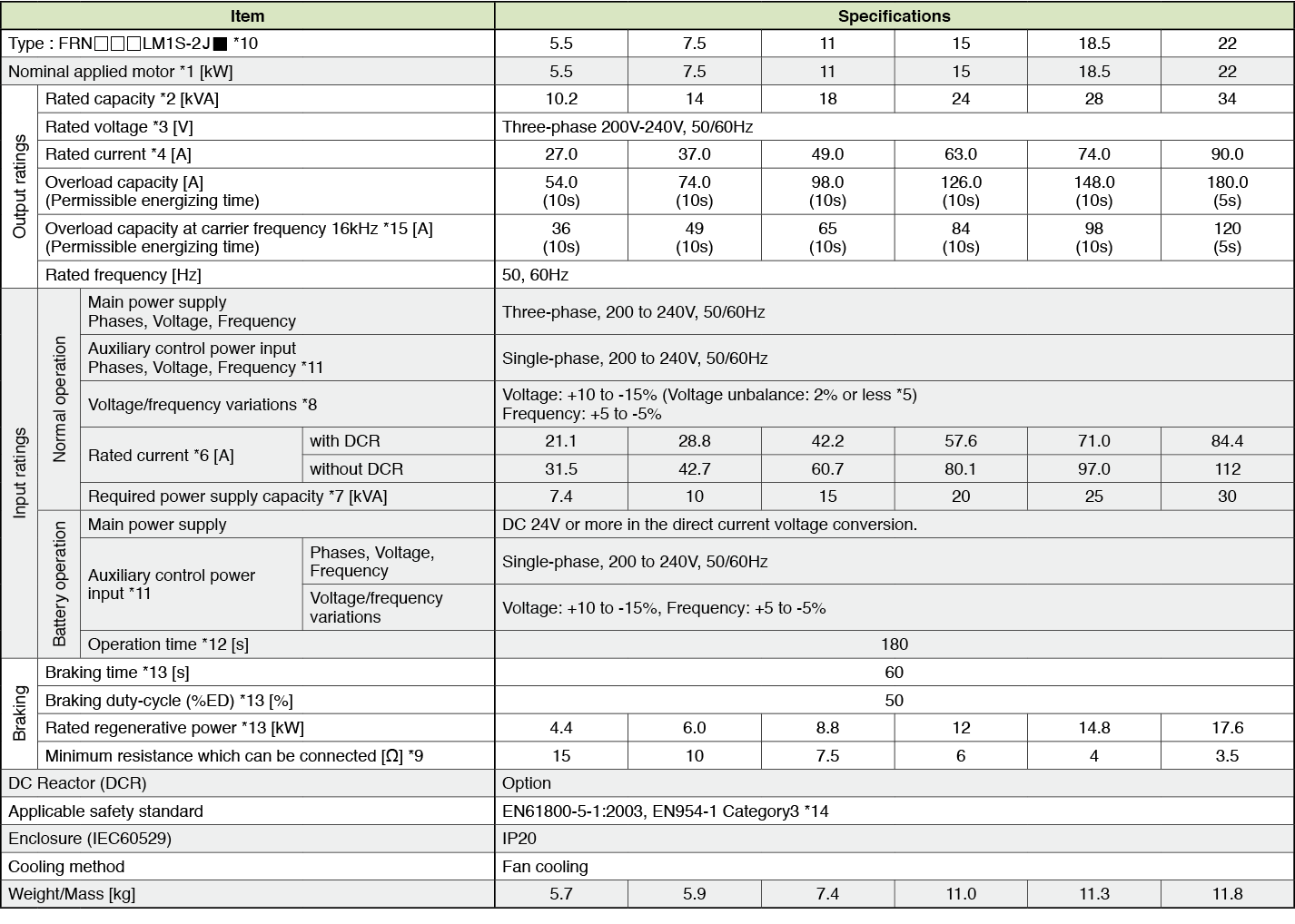
Basic type (Three-phase 200V)

-
Note1
-
Fuji’s 4-pole standard motor
-
Note2
-
Rated capacity is calculated by regarding the output rated voltage as 220V for three-phase 200V series.
-
Note3
-
Output voltage cannot exceed the power supply voltage.
-
Note4
-
It is a value in the condition of the carrier frequency 10kHz and the ambient temperature 45°C. Select the inverter capacity such that the square average current in cycle operation is 80% or less of the rated current of an inverter.
-
Note5
-
Voltage unbalance [%] = (Max. voltage [V] - Min. voltage [V])/ Three-phase average voltage [V] x 67 (IEC61800-3)
-
Note6
-
The power supply capacity is 500kVA (ten times the inverter capacity when the inverter capacity exceeds 50kVA), and the calculation value when connecting with the power supply of %X=5%.
-
Note7
-
Obtained when a DC Reactor is used.
-
Note8
-
An acceptable variation of the main power supply and the control power supply assistance input.
-
Note9
-
The admissible error of minimum resistance is ±5%.
-
Note10
-
-
Note11
-
The same AC power as the main power supply input is connected for the backup of the control circuit power source.
-
Note12
-
It is a value in the condition of the carrier frequency 10kHz and the ambient temperature 45°C. Use the inverter such that the square average current in battery
operation is 80% or less of the rated current of an inverter.
-
Note13
-
Braking time and duty cycle (%ED) are defined by cycle operation at the rated regenerative power as shown in the figure below.
-
Note14
-
The inverter that last 2 digits of a software version are from 50 to 99 corresponds to this standard.
-
Note15
-
When output exceeds this overload capacity at carrier frequency 16kHz, carrier frequency is reduced automatically. The reduced carrier frequency is maintained until an inverter stops.
Basic type (Three-phase 400V)

-
Note1
-
Fuji’s 4-pole standard motor
-
Note2
-
Rated capacity is calculated by regarding the output rated voltage as 440V for three-phase 400V series.
-
Note3
-
Output voltage cannot exceed the power supply voltage.
-
Note4
-
It is a value in the condition of the carrier frequency 10kHz and the ambient temperature 45°C. Select the inverter capacity such that the square average current in cycle operation is 80% or less of the rated current of an inverter.
-
Note5
-
Voltage unbalance [%] = (Max. voltage [V] - Min. voltage [V])/ Three-phase average voltage [V] x 67 (IEC61800-3)
-
Note6
-
The power supply capacity is 500kVA (ten times the inverter capacity when the inverter capacity exceeds 50kVA), and the calculation value when connecting with the power supply of %X=5%.
-
Note7
-
Obtained when a DC Reactor is used.
-
Note8
-
An acceptable variation of the main power supply and the control power supply assistance input.
-
Note9
-
The admissible error of minimum resistance is ±5%.
-
Note10
-
-
Note11
-
It is necessary to change the power-supply voltage change connector on the power supply printed wiring board depend on the power-supply voltage.
-
Note12
-
30kW or less
The same AC power as the main power supply input is connected for the backup of the control circuit power source.
37kW or more
The same AC power as the main power supply input is connected for the control circuit, the fan, and the contactor.
The inverter doesn’t operate if the power supply is not input to the auxiliary control power input. Please supply power.
-
Note13
-
It is a value in the condition of the carrier frequency 10kHz and the ambient temperature 45°C. Use the inverter such that the square average current in battery operation is 80% or less of the rated current of an inverter.
-
Note14
-
Braking time and duty cycle (%ED) are defined by cycle operation at the rated regenerative power as shown in the figure below.
-
Note15
-
The inverter that last 2 digits of a software version are from 50 to 99 corresponds to this standard.
-
Note16
-
When output exceeds this overload capacity at carrier frequency 16kHz, carrier frequency is reduced automatically. The reduced carrier frequency is maintained until an inverter stops.
Basic type (Single-phase 200V)

-
Note1
-
Fuji’s 4-pole standard motor
-
Note2
-
Rated capacity is calculated by regarding the output rated voltage as 220V.
-
Note3
-
Output voltage cannot exceed the power supply voltage.
-
Note4
-
It is a value in the condition of the carrier frequency 10kHz and the ambient temperature 45°C. Select the inverter capacity such that the square average current in cycle operation is 80% or less of the rated current of an inverter.
-
Note5
-
The power supply capacity is 500kVA (ten times the inverter capacity when the inverter capacity exceeds 50kVA), and the calculation value when connecting with the power supply of %X=5%.
-
Note6
-
Obtained when a DC Reactor is used.
-
Note7
-
An acceptable variation of the main power supply and the control power supply assistance input.
-
Note8
-
The admissible error of minimum resistance is ±5%.
-
Note9
-
-
Note10
-
The same AC power as the main power supply input is connected for the backup of the control circuit power source.
-
Note11
-
It is a value in the condition of the carrier frequency 10kHz and the ambient temperature 45°C. Use the inverter such that the square average current in battery operation is 80% or less of the rated current of an inverter.
-
Note12
-
Braking time and duty cycle (%ED) are defined by cycle operation at the rated regenerative power as shown in the figure below.

-
Note13
-
The inverter that last 2 digits of a software version are from 50 to 99 corresponds to this standard.
-
Note14
-
When output exceeds this overload capacity at carrier frequency 16kHz, carrier frequency is reduced automatically. The reduced carrier frequency is maintained until an inverter stops.
This model is not available in your region.
For more information regarding this product, please contact us via the inquiry form.
Basic type (Three-phase 400V)
-
Note1
-
Fuji’s 4-pole standard motor
-
Note2
-
Rated capacity is calculated by regarding the output rated voltage as 440V for three-phase 400V series.
-
Note3
-
Output voltage cannot exceed the power supply voltage.
-
Note4
-
It is a value in the condition of the carrier frequency 10kHz and the ambient temperature 45°C. Select the inverter capacity such that the square average current in cycle operation is 80% or less of the rated current of an inverter.
-
Note5
-
Voltage unbalance [%] = (Max. voltage [V] - Min. voltage [V])/ Three-phase average voltage [V] x 67 (IEC61800-3)
-
Note6
-
The power supply capacity is 500kVA (ten times the inverter capacity when the inverter capacity exceeds 50kVA), and the calculation value when connecting with the power supply of %X=5%.
-
Note7
-
Obtained when a DC Reactor is used.
-
Note8
-
An acceptable variation of the main power supply and the control power supply assistance input.
-
Note9
-
The admissible error of minimum resistance is ±5%.
-
Note10
-
It is necessary to change the power-supply voltage change connector on the power supply printed wiring board depend on the power-supply voltage.
-
Note11
-
30kW or less
The same AC power as the main power supply input is connected for the backup of the control circuit power source.
37kW or more
The same AC power as the main power supply input is connected for the control circuit, the fan, and the contactor.
The inverter doesn’t operate if the power supply is not input to the auxiliary control power input. Please supply power.
-
Note12
-
It is a value in the condition of the carrier frequency 10kHz and the ambient temperature 45°C. Use the inverter such that the square average current in battery
operation is 80% or less of the rated current of an inverter.
-
Note13
-
Braking time and duty cycle (%ED) are defined by cycle operation at the rated regenerative power as shown in the figure below.
-
Note14
-
The inverter that last 2 digits of a software version are from 50 to 99 corresponds to this standard.
-
Note15
-
When output exceeds this overload capacity at carrier frequency 16kHz, carrier frequency is reduced automatically. The reduced carrier frequency is maintained until
an inverter stops.
Basic type (Three-phase 200V)

-
Note1
-
Fuji’s 4-pole standard motor
-
Note2
-
Rated capacity is calculated by regarding the output rated voltage as 220V for three-phase 200V series.
-
Note3
-
Output voltage cannot exceed the power supply voltage.
-
Note4
-
It is a value in the condition of the carrier frequency 10kHz and the ambient temperature 45°C. Select the inverter capacity such that the square average current in cycle operation is 80% or less of the rated current of an inverter.
-
Note5
-
Voltage unbalance [%] = (Max. voltage [V] - Min. voltage [V])/ Three-phase average voltage [V] x 67 (IEC61800-3)
-
Note6
-
The power supply capacity is 500kVA (ten times the inverter capacity when the inverter capacity exceeds 50kVA), and the calculation value when connecting with the power supply of %X=5%.
-
Note7
-
Obtained when a DC Reactor is used.
-
Note8
-
An acceptable variation of the main power supply and the control power supply assistance input.
-
Note9
-
The admissible error of minimum resistance is ±5%.
-
Note10
-
-
Note11
-
The same AC power as the main power supply input is connected for the backup of the control circuit power source.
-
Note12
-
It is a value in the condition of the carrier frequency 10kHz and the ambient temperature 45°C. Use the inverter such that the square average current in battery operation is 80% or less of the rated current of an inverter.
-
Note13
-
Braking time and duty cycle (%ED) are defined by cycle operation at the rated regenerative power as shown in the figure below.
-
Note14
-
The inverter that last 2 digits of a software version are from 50 to 99 corresponds to this standard.
-
Note15
-
When output exceeds this overload capacity at carrier frequency 16kHz, carrier frequency is reduced automatically. The reduced carrier frequency is maintained until an inverter stops.
Basic type (Three-phase 400V)

-
Note1
-
Fuji’s 4-pole standard motor
-
Note2
-
Rated capacity is calculated by regarding the output rated voltage as 440V for three-phase 400V series.
-
Note3
-
Output voltage cannot exceed the power supply voltage.
-
Note4
-
It is a value in the condition of the carrier frequency 10kHz and the ambient temperature 45°C. Select the inverter capacity such that the square average current in cycle operation is 80% or less of the rated current of an inverter.
-
Note5
-
Voltage unbalance [%] = (Max. voltage [V] - Min. voltage [V])/ Three-phase average voltage [V] x 67 (IEC61800-3)
-
Note6
-
The power supply capacity is 500kVA (ten times the inverter capacity when the inverter capacity exceeds 50kVA), and the calculation value when connecting with the power supply of %X=5%.
-
Note7
-
Obtained when a DC Reactor is used.
-
Note8
-
An acceptable variation of the main power supply and the control power supply assistance input.
-
Note9
-
The admissible error of minimum resistance is ±5%.
-
Note10
-
-
Note11
-
It is necessary to change the power-supply voltage change connector on the power supply printed wiring board depend on the power-supply voltage.
-
Note12
-
30kW or less
The same AC power as the main power supply input is connected for the backup of the control circuit power source.
37kW or more
The same AC power as the main power supply input is connected for the control circuit, the fan, and the contactor.
The inverter doesn’t operate if the power supply is not input to the auxiliary control power input. Please supply power.
-
Note13
-
It is a value in the condition of the carrier frequency 10kHz and the ambient temperature 45°C. Use the inverter such that the square average current in battery operation is 80% or less of the rated current of an inverter.
-
Note14
-
Braking time and duty cycle (%ED) are defined by cycle operation at the rated regenerative power as shown in the figure below.
-
Note15
-
The inverter that last 2 digits of a software version are from 50 to 99 corresponds to this standard.
-
Note16
-
When output exceeds this overload capacity at carrier frequency 16kHz, carrier frequency is reduced automatically. The reduced carrier frequency is maintained until an inverter stops.
Basic type (Single-phase 200V)

-
Note1
-
Fuji’s 4-pole standard motor
-
Note2
-
Rated capacity is calculated by regarding the output rated voltage as 220V.
-
Note3
-
Output voltage cannot exceed the power supply voltage.
-
Note4
-
It is a value in the condition of the carrier frequency 10kHz and the ambient temperature 45°C. Select the inverter capacity such that the square average current in cycle operation is 80% or less of the rated current of an inverter.
-
Note5
-
The power supply capacity is 500kVA (ten times the inverter capacity when the inverter capacity exceeds 50kVA), and the calculation value when connecting with the power supply of %X=5%.
-
Note6
-
Obtained when a DC Reactor is used.
-
Note7
-
An acceptable variation of the main power supply and the control power supply assistance input.
-
Note8
-
The admissible error of minimum resistance is ±5%.
-
Note9
-
-
Note10
-
The same AC power as the main power supply input is connected for the backup of the control circuit power source.
-
Note11
-
It is a value in the condition of the carrier frequency 10kHz and the ambient temperature 45°C. Use the inverter such that the square average current in battery operation is 80% or less of the rated current of an inverter.
-
Note12
-
Braking time and duty cycle (%ED) are defined by cycle operation at the rated regenerative power as shown in the figure below.

-
Note13
-
The inverter that last 2 digits of a software version are from 50 to 99 corresponds to this standard.
-
Note14
-
When output exceeds this overload capacity at carrier frequency 16kHz, carrier frequency is reduced automatically. The reduced carrier frequency is maintained until an inverter stops.
Basic type (Three-phase 200V)
-
Note1
-
Fuji’s 4-pole standard motor
-
Note2
-
Rated capacity is calculated by regarding the output rated voltage as 220V for three-phase 200V series.
-
Note3
-
Output voltage cannot exceed the power supply voltage.
-
Note4
-
It is a value in the condition of the carrier frequency 10kHz and the ambient temperature 45°C. Select the inverter capacity such that the square average current in cycle operation is 80% or less of the rated current of an inverter.
-
Note5
-
Voltage unbalance [%] = (Max. voltage [V] - Min. voltage [V])/ Three-phase average voltage [V] x 67 (IEC61800-3)
-
Note6
-
The power supply capacity is 500kVA (ten times the inverter capacity when the inverter capacity exceeds 50kVA), and the calculation value when connecting with the power supply of %X=5%.
-
Note7
-
Obtained when a DC Reactor is used.
-
Note8
-
An acceptable variation of the main power supply and the control power supply assistance input.
-
Note9
-
The admissible error of minimum resistance is ±5%.
-
Note10
-
-
Note11
-
The same AC power as the main power supply input is connected for the backup of the control circuit power source.
-
Note12
-
It is a value in the condition of the carrier frequency 10kHz and the ambient temperature 45°C. Use the inverter such that the square average current in battery operation is 80% or less of the rated current of an inverter.
-
Note13
-
Braking time and duty cycle (%ED) are defined by cycle operation at the rated regenerative power as shown in the figure below.
-
Note14
-
The inverter that last 2 digits of a software version are from 50 to 99 corresponds to this standard.
-
Note15
-
When output exceeds this overload capacity at carrier frequency 16kHz, carrier frequency is reduced automatically. The reduced carrier frequency is maintained until an inverter stops.
Basic type (Three-phase 400V)

-
Note1
-
Fuji’s 4-pole standard motor
-
Note2
-
Rated capacity is calculated by regarding the output rated voltage as 440V for three-phase 400V series.
-
Note3
-
Output voltage cannot exceed the power supply voltage.
-
Note4
-
It is a value in the condition of the carrier frequency 10kHz and the ambient temperature 45°C. Select the inverter capacity such that the square average current in cycle operation is 80% or less of the rated current of an inverter.
-
Note5
-
Voltage unbalance [%] = (Max. voltage [V] - Min. voltage [V])/ Three-phase average voltage [V] x 67 (IEC61800-3)
-
Note6
-
The power supply capacity is 500kVA (ten times the inverter capacity when the inverter capacity exceeds 50kVA), and the calculation value when connecting with the power supply of %X=5%.
-
Note7
-
Obtained when a DC Reactor is used.
-
Note8
-
An acceptable variation of the main power supply and the control power supply assistance input.
-
Note9
-
The admissible error of minimum resistance is ±5%.
-
Note10
-
-
Note11
-
It is necessary to change the power-supply voltage change connector on the power supply printed wiring board depend on the power-supply voltage.
-
Note12
-
30kW or less
The same AC power as the main power supply input is connected for the backup of the control circuit power source.
37kW or more
The same AC power as the main power supply input is connected for the control circuit, the fan, and the contactor.
The inverter doesn’t operate if the power supply is not input to the auxiliary control power input. Please supply power.
-
Note13
-
It is a value in the condition of the carrier frequency 10kHz and the ambient temperature 45°C. Use the inverter such that the square average current in battery operation is 80% or less of the rated current of an inverter.
-
Note14
-
Braking time and duty cycle (%ED) are defined by cycle operation at the rated regenerative power as shown in the figure below.
-
Note15
-
The inverter that last 2 digits of a software version are from 50 to 99 corresponds to this standard.
-
Note16
-
When output exceeds this overload capacity at carrier frequency 16kHz, carrier frequency is reduced automatically. The reduced carrier frequency is maintained until an inverter stops.
Basic type (Single-phase 200V)
-
Note1
-
Fuji’s 4-pole standard motor
-
Note2
-
Rated capacity is calculated by regarding the output rated voltage as 220V.
-
Note3
-
Output voltage cannot exceed the power supply voltage.
-
Note4
-
It is a value in the condition of the carrier frequency 10kHz and the ambient temperature 45°C. Select the inverter capacity such that the square average current in cycle operation is 80% or less of the rated current of an inverter.
-
Note5
-
The power supply capacity is 500kVA (ten times the inverter capacity when the inverter capacity exceeds 50kVA), and the calculation value when connecting with the power supply of %X=5%.
-
Note6
-
Obtained when a DC Reactor is used.
-
Note7
-
An acceptable variation of the main power supply and the control power supply assistance input.
-
Note8
-
The admissible error of minimum resistance is ±5%.
-
Note9
-
-
Note10
-
The same AC power as the main power supply input is connected for the backup of the control circuit power source.
-
Note11
-
It is a value in the condition of the carrier frequency 10kHz and the ambient temperature 45°C. Use the inverter such that the square average current in battery operation is 80% or less of the rated current of an inverter.
-
Note12
-
Braking time and duty cycle (%ED) are defined by cycle operation at the rated regenerative power as shown in the figure below.

-
Note13
-
The inverter that last 2 digits of a software version are from 50 to 99 corresponds to this standard.
-
Note14
-
When output exceeds this overload capacity at carrier frequency 16kHz, carrier frequency is reduced automatically. The reduced carrier frequency is maintained until an inverter stops.
Basic type (Three-phase 400V)

-
Note1
-
Fuji’s 4-pole standard motor
-
Note2
-
Rated capacity is calculated by regarding the output rated voltage as 440V for three-phase 400V series.
-
Note3
-
Output voltage cannot exceed the power supply voltage.
-
Note4
-
It is a value in the condition of the carrier frequency 10kHz and the ambient temperature 45°C. Select the inverter capacity such that the square average current in cycle operation is 80% or less of the rated current of an inverter.
-
Note5
-
Voltage unbalance [%] = (Max. voltage [V] - Min. voltage [V])/ Three-phase average voltage [V] x 67 (IEC61800-3)
-
Note6
-
The power supply capacity is 500kVA (ten times the inverter capacity when the inverter capacity exceeds 50kVA), and the calculation value when connecting with the power supply of %X=5%.
-
Note7
-
Obtained when a DC Reactor is used.
-
Note8
-
An acceptable variation of the main power supply and the control power supply assistance input.
-
Note9
-
The admissible error of minimum resistance is ±5%.
-
Note11
-
It is necessary to change the power-supply voltage change connector on the power supply printed wiring board depend on the power-supply voltage.
-
Note12
-
30kW or less
The same AC power as the main power supply input is connected for the backup of the control circuit power source.
37kW or more
The same AC power as the main power supply input is connected for the control circuit, the fan, and the contactor.
The inverter doesn’t operate if the power supply is not input to the auxiliary control power input. Please supply power.
-
Note13
-
It is a value in the condition of the carrier frequency 10kHz and the ambient temperature 45°C. Use the inverter such that the square average current in battery operation is 80% or less of the rated current of an inverter.
-
Note14
-
Braking time and duty cycle (%ED) are defined by cycle operation at the rated regenerative power as shown in the figure below.
-
Note15
-
The inverter that last 2 digits of a software version are from 50 to 99 corresponds to this standard.
-
Note16
-
When output exceeds this overload capacity at carrier frequency 16kHz, carrier frequency is reduced automatically. The reduced carrier frequency is maintained until an inverter stops.
AC Drives (Low Voltage) Support

Download documents
Column

Understanding application, benefits, basic structure, case study, types, and Fuji Electric's inverters with this video.
December 27,2021

Understanding the basics: Differences between inverters and converters
January 20,2021

How and what does an inverter take control of? A brief explanation to grasp the basic structure.
January 20,2021

The fundamentals of inverters and their uses.
January 20,2021