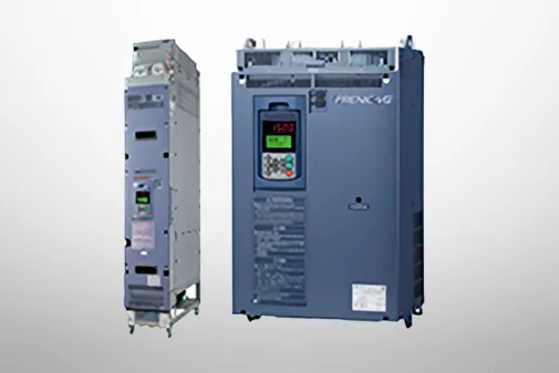
FRENIC-MEGA (G2)
Specifications | Common Specifications


-
Common Specifications
| Item | Explanation | Remarks | ||||
|---|---|---|---|---|---|---|
| Output | Adjustment | Maximum output frequency |
5 to 599 Hz variable setting | |||
| Base frequency |
5 to 599 Hz variable setting (in conjunction with maximum output frequency) | |||||
| Number of motor poles setting |
2 to 128 poles | |||||
| Starting frequency |
0.1 to 60.0 Hz variable setting (0.0 Hz when performing speed sensorless vector control/vector control with speed sensor) | |||||
| Carrier frequency |
• 0.75 to 16 kHz variable setting HHD specification: 0.4 to 55 kW (type: 0003 to 0288 (200 V), type: 0002 to 0179 (400 V)) HND specification: 5.5 to 18.5 kW (type: 0032 to 0088 (200 V), type: 0018 to 0045 (400 V)) • 0.75 to 10 kHz variable setting HHD specification: 75 to 630 kW (type: 0346 to 0432 (200 V), type: 0217 to 1480 (400 V)) HND specification: 22 to 55 kW (type: 0115 to 0288 (200 V), type: 0060 to 0179 (400 V)) HD specification: 30 to 55 kW (type: 0085 to 0179 (400 V)) • 0.75 to 6 kHz variable setting HND specification: 75 to 630 kW (type: 0346 to 0432 (200 V), type: 0217 to 1480 (400 V)) HD specification: 75 to 630 kW (type: 0217 to 1480 (400 V)) ND specification: 30 to 630 kW (type: 0085 to 1480 (400 V)) Note)The carrier frequency may automatically lower depending upon the ambient temperature or the output current to protect the inverter. (The automatic lowering function can be disabled.) |
|||||
| Output frequency accuracy |
• Analog setting : ±0.2% of maximum output frequency (at 25 ±10 °C) (77 ±18 °F) • Keypad setting : ±0.01% of maximum output frequency (at 10 to +50 °C) (14 ±22 °F) |
|||||
| Frequency setting resolution |
• Analog setting : 1/3000 of maximum output frequency • Keypad setting : 0.01 Hz • Link setting : 1/20000 of maximum output frequency or 0.01 Hz (fixed) |
|||||
| Synchronous motors |
When performing V/f control with sensor(Note 1) When performing dynamic torque vector control with sensor(Note 2) |
Speed control Range | • 1:20(Note 1), 1:200(Note 2) (Minimum speed: Nominal speed) • 1:2 (fixed torque area : fixed output area) |
|||
| Speed control accuracy |
• Analog setting: ±0.2% of maximum output frequency or below (at 25 ±10 °C) • Digital setting: ±0.01% of maximum output frequency or below (at 10 to +50 °C) |
|||||
| When performing sensorless vector control |
Speed control Range |
• 1:200 (Minimum speed: Nominal speed) • 1:2 (fixed torque area : fixed output area) |
||||
| Speed control accuracy |
• Analog setting: ±0.5% of maximum output frequency or below (at 25 ±10 °C) • Digital setting: ±0.5% of maximum output frequency or below (at 10 to +50 °C) |
|||||
| When performing vector control with sensor |
Speed control Range | • 1:1500 (Minimum speed: Nominal speed) • 1:16 (fixed torque area : fixed output area) |
||||
| Speed control accuracy |
• Analog setting: ±0.2% of maximum output frequency or below (at 25 ±10 °C) • Digital setting: ±0.01% of maximum output frequency or below (at 10 to +50 °C) |
|||||
| When performing sensorless vector control |
Speed control Range |
• 1:10 (Minimum speed: Nominal speed) • 1:2 (Limited by maximum output voltage) |
||||
| Speed control accuracy |
• Analog setting: ±0.5% of nominal speed or below (at 25 ±10 °C) • Digital setting: ±0.5% of nominal speed or below (at -10 to +50 °C) |
|||||
| When performing vector control with sensor |
Speed control Range |
• 1:1500 (Minimum speed: Nominal speed) • 1:2 (Limited by maximum output voltage) |
||||
| Speed control accuracy |
• Analog setting: ±0.2% of maximum output frequency (at 25 ±10 °C) • Digital setting: ±0.01% of maximum output frequency (at 10 to +50 °C) |
|||||
| Control | Control method |
• V/f control • Dynamic torque vector control • V/f control with sensor, dynamic torque vector control with sensor • Sensorless vector control • Vector control with sensor • Sensorless vector control (synchronous motors) • Vector control with sensor (synchronous motors) |
||||
| Voltage/frequency characteristics |
200V series | • The base frequency and maximum output frequency are common, and the voltage can be set between 80 and 240 V. • AVR control can be turned ON or OFF. • Non-linear V/f setting (3 points): The desired voltage (0 to 240 V) and frequency (0 to 599 Hz) can be set. |
||||
| 400V series | • The base frequency and maximum output frequency are common, and the voltage can be set between 160 and 500 V. • AVR control can be turned ON or OFF. • Non-linear V/f setting (3 points): The desired voltage (0 to 500 V) and frequency (0 to 599 Hz) can be set. |
|||||
| Torque boost | • Auto torque boost (for constant torque load) • Manual torque boost: The desired torque boost value (0.0 to 20.0%) can be set. • The applicable load can be selected (for constant torque load, quadratic-torque load) |
|||||
| Starting torque (HHD specification) |
• FRN0115G2S-2G/FRN0060G2■-4G or below 200% or higher, • FRN0146G2S-2G/FRN0085G2■-4G or above 180% or higher set frequency: 0.3 Hz, when performing V/f control (base frequency: 50 Hz, slip compensation/auto torque boost) |
|||||
| Running・operation | Key operation: | Start and stop with  and and  keys (LED keypad) keys (LED keypad)Start and stop with  , ,  , and keys (optional multi-function keypad) , and keys (optional multi-function keypad) |
||||
| External signals: Forward (reverse) rotation, start/stop commands [2-wire/3-wire operable], (digital input) coast to stop command, external alarm, alarm reset, etc. | ||||||
| Link operation: Operation through RS-485, field bus communication (option) | ||||||
| Run command switching : Remote/local switching, link switching | ||||||
| [RUN] key memory : Memorizes the state of the key in the event of a power failure during operation using the keypad, and resumes operation after power is restored. |
||||||
| Frequency setting |
Keypad operation : Using  and and  keys keys |
|||||
| External potentiometer: Using external frequency command potentiometer(external resistor of 1 to 5 kΩ, 1/2 W) | ||||||
| Analog input : | Voltage input (terminal [12], [V2], [C1] (V3 function)) 0 to ±10 VDC (±5 VDC)/0 to ±100% 0 to +10 VDC (+5 VDC)/0 to +100% (+1 to +5 VDC can also be adjusted with bias, analog input gain) Voltage input (terminal [C1] (C1 function)) 4 to 20 mA DC/0 to 100%, 0 to 20 mA DC/0 to 100% 4 to 20 mA DC/-100 to +100%, 0 to 20 mA DC/-100 to +100% |
|||||
| Item | Explanation | Remarks | |||
|---|---|---|---|---|---|
| Control | Frequency setting |
UP/DOWN operation: Frequency can be increased or decreased while the digital input signal is ON. The frequency recorded with digital input “STZ” can be cleared. |
|||
| Multistep frequency selection: | Selectable from 16 different frequencies (step 0 to 15) | ||||
| Pattern operation: | The inverter runs automatically according to the previously specified run time, rotation direction, acceleration/deceleration time and reference frequency. Up to 7 stages can be specified. |
||||
| Link operation: | Setting through RS-485, field bus communication (option) (built in as standard) | ||||
| Frequency setting switching: | Two types of frequency settings can be switched with an external signal (digital input). Remote/local switching, link switching | ||||
| Auxiliary frequency setting: | Can be selected by adding and entering the respective terminal [12], [C1], or [V2] inputs. | ||||
| Operation at a specified ratio: | The ratio can be set with an analog input signal.. | ||||
| Inverse operation: | Can be switched from “0 to +10 VDC/0 to 100%” to 10 to 0 VDC/0 to 100%” from an external source. Can be switched from “4 to 20 mA DC/0 to 100%” to “20 to 4 mA DC/0 to 100%” from an external source. Can be switched from “0 to 20 mA DC/0 to 100%” to “20 to 0 mA DC/0 to 100%” from an external source. |
||||
| Pulse train input: (standard) |
Pulse input = terminal [X6], [X7], forward/reverse pulse, pulse + rotation direction Complementary output: Max. 100 kHz Open collector output: Max. 30 kHz |
||||
| Pulse train input: (option) |
PG interface option, forward/reverse pulse, pulse + rotation direction Complementary output: Max. 100 kHz Open collector output: Max. 30 kHz |
||||
| Acceleration/ deceleration time |
Setting range: | Setting range from 0.00 to 6000 s | |||
| Switching: | The four types of acceleration/deceleration time can be set or selected individually (switchable during operation). | ||||
| Acceleration/deceleration pattern: | |||||
| Deceleration mode (coast to stop): | Shutoff of the run command lets the motor coast to a stop. | ||||
| Forced stop deceleration time: Deceleration stop in exclusive deceleration time by forced stop (STOP). • Dedicated acceleration/deceleration time for jogging: • It is possible to switch between acceleration/deceleration time = 0 with acceleration/deceleration operation cancel “BPS”. |
|||||
| Frequency limiter (upper limit and lower limit frequencies) |
• Specifies the upper and lower frequencies in Hz. • Processing can be selected when the reference frequency is less than the lower limit (F16). (The output frequency will be maintained at the lower limit/motor decelerates and stops.) • Setting is possible with analog input (terminal【12】,【C1】,【V2】,【V3】). |
||||
| Frequency/ PID command bias |
• Frequency: Set between 0 and ±200% • PID command: Set between 0 to ±100% |
||||
| Analog input |
• Gain: Setting range from 0 to 400% • Offset: Setting range from 5.0 to +5.0% • Filter: Setting range from 0.00 to 5.00s |
||||
| Jump frequency |
Six operation points and their common jump width (0 to 30.0 Hz) can be set. | ||||
| Ready for jogging |
Operation with key (LED keypad), or keys (Multi function keypad), or digital contact inputs “FWD” or “REV” (Exclusive acceleration/deceleration time setting, exclusive frequency setting) |
||||
| Restart mode after momentary power failure |
• Trip immediately: Trip immediately at the time of power failure. • Trip after recovery from power failure: Coast to a stop at the time of power failure and trip when the power is recovered. • Trip after decelerate to stop: Deceleration stop at power failure, and trip after stoppage • Continue to run: Operation is continued using the load inertia energy. • Start at the frequency selected before momentary power failure: Free run at power failure and start after power recovery at the frequency selected before momentary stop. • Start at starting frequency: Free run at power failure and start at the starting frequency after power recovery. • Start at frequency of power recovery: Free run at power failure, and start after power recovery by searching for the speed. |
||||
| Current limiting |
Hardware current limiter |
Current is limited with hardware to prevent overcurrent trip due to high-speed load fluctuations or momentary power failure which cannot be handled with software current limiting. (This limiter can be canceled.) |
|||
| Software current limiter |
Automatically reduces the frequency so that the output current becomes lower than the preset operation level. (This limiter can be canceled.) The operation can be selected (operation at constant speed only, operation when accelerating and at constant speed). |
||||
| Operation by commercial power supply |
• With commercial power selection commands (“SW50”, “SW60”), the inverter outputs 50/60 Hz. • Commercial switching sequence built in |
||||
| Slip compensation |
Compensates for decrease in speed according to the load. | ||||
| Droop control |
Decreases the speed according to the load torque. | ||||
| Torque limit control |
• Switchable between 1st and 2nd torque limit values. • Torque limiting/torque current limiting/power limiting for each quadrant • Analog torque limit input |
||||
| PID control |
• PID processor for process control/dancer control • Switch normal/inverse operation • Command: Keypad, analog input (terminals【12】,【C1】,【V2】,【V3】), multi-stage setting (selectable from 3 options), RS-485 communication, fieldbus communication (optional) • Feedback value: Analog input (terminals【12】,【C1】,【V2】,【V3】) • Alarm output (absolute value alarm, deviation alarm) • PID feedback error detection • Sensor input scaling function • Sensor input conversion/calculation function • Low liquid level stop function (pressurized operation possible before low liquid level stop) • Automatic frequency update function for stoppage due to small water quantity • Anti reset wind up function • Output limiter • Integration reset/hold • PID constant auto tuning function for process control PID controlle • Built-in external PID controller: 3 sets |
||||
| Retry | • Automatically releases the trip state and resumes operation up to the set number of times without outputting a batch alarm even if the protective function to be retried is activated. • Can be set up to 20 times (configurable by function code). • Can set the wait time before resetting. • Can set the alarm to be retried |
||||
| Item | Explanation | Remarks | ||
|---|---|---|---|---|
| Control | Simulated operation mode | Sequence check is possible without inverter output. | ||
| Start check function | To ensure safety, the presence or absence of an operation command is checked at power-on, at alarm reset, and when switching operation command methods. An alarm is displayed if an operation command has been input. | |||
| Multifunction key | During the operation mode, the multifunction key “M/SHIFT” on LED keypads (TP-E2) can be used as an input method to activate the input terminal function like the X terminal. | |||
| Traceback | Data immediately before a trip are automatically saved such as frequency, voltage, current (user-selectable). Saved data is displayed and analyzed with the PC loader. | |||
| Display | Running/stopping | Speed monitor (reference frequency, output frequency, motor speed, load shaft speed, line speed, and speed indication percentage), output current [A], output voltage [V], calculated torque [%], power consumption [kW], PID command value, PID feedback value, PID output, load factor [%], motor output [kW], torque current (%), magnetic flux command (%), analog input monitor, input watt hour |
||
| Inverter lifetime alarm |
|
|||
| Cumulative operating status |
|
|||
| Trip | Displays the cause of a trip. | |||
| Light alarm | The cause of light alarms is displayed. | |||
| During operation, when trip occurs |
|
|||
| Protective functions | Overcurrent protection | Stops the inverter to protect it from overcurrent caused by an overload. | OC1 OC2 OC3 | |
| Short circuit protection | Stops the inverter to protect it from overcurrent caused by shorting of the output circuit. | |||
| Ground fault protection | Detects the overcurrent caused by the ground fault of the output circuit and stops the inverter Protection may be disabled if the power is turned ON with the ground fault still occurring. | |||
| Detects output current zero-phase current, and stops the inverter to protect it from overcurrent caused by an output circuit ground fault. (5.5 kW or higher) | EF | |||
| Overvoltage protection | Stops the inverter if a DC intermediate circuit overvoltage (400V series: 800 VDC, 200V series: 400 VDC) is detected. The inverter cannot be protected if an excessively large voltage is applied by accident. | OV1 OV2 OV3 | ||
| Undervoltage protection | Stops the inverter if a drop in DC intermediate circuit voltage (400V series: 400 VDC, 200V series: 200 VDC) is detected. However, this is disabled based on the restart after momentary power failure setting. Furthermore, operation is possible (regenerative operation only) at a voltage level lower than that above when performing battery operation. | LV | ||
| Input phase loss protection | Stops the inverter if input voltage phase loss or interphase unbalance factor is detected. If the load is light, or when a DC reactor is connected, input phase loss may not function. | Lin | ||
| Output phase loss protection | Stops the inverter if inverter output phase loss is detected during operation. This protective function also functions during auto tuning and during magnetic pole position tuning. (Operation selection possible) |
OPL | ||
| Overheat protection | Stops the inverter if a cooling fan fault, or cooling fin overheating when an overload occurs is detected. | OH1 | ||
| Stops the inverter if inverter unit internal charging resistor overheating is detected. | OH3 | |||
| Stops the inverter if inverter unit internal charging resistor overheating is detected. | OH6 | |||
| By setting the braking resistor electronic thermal overload relay function, the inverter is stopped to protect the braking resistor from overheating. | dbH | |||
| Inverter overload protection | Stops the inverter if overheating is detected by calculating the IGBT internal temperature from the output current and detected internal temperature. | OLU | ||
| External alarm input | Stops the inverter and displays an error if a digital input signal (THR) is input. | OH2 | ||
| Fuse blown | Stops the inverter and displays an error if a fuse is blown inside the inverter. (75 kW or higher (type: 0346 to 0432 (200 V))) (90 kW or higher (type: 0261 to 1480 (400 V))) | FUS | ||
| Charging circuit fault | Stops the inverter and displays an error if an inverter charging circuit error is detected. (Type: 0008 to 0432(200 V), Type: 0004 to 1480 (400 V)) | PbF | ||
| Braking transistor fault | Stops the inverter and displays an error if a braking transistor error is detected.(Type: 0003 to 0288(200 V), Type: 0002 to 0217(400 V)) | dbA | ||
| Motor protection | Electronic thermal overload relay | Stops the inverter if a motor overload is detected by setting the electronic thermal overload relay. Protects general-purpose motors and inverter motors in the entire frequency range. (The operation level and thermal time constant (0.5 to 75.0 minutes) can be set.) | OL1 to OL4 | |
| PTC/NTC thermistor | The motor temperature is detected by the PTC/NTC thermistor, and the inverter is stopped if overheating is detected. To enable this function, connect the PTC/NTC thermistor between terminals【V2】and【11】, and enable the switch on the control board. |
OH4 | ||
| NTC thermistor wire break | The inverter is stopped and an error is displayed if a wire break is detected at the NTC thermistor connected between terminals [V2] and [11]. | nrb | ||
| Memory error | When the power is turned ON, a data check is performed when writing data, and an error is displayed if a memory error is detected. | Er1 | ||
| Keypad communication error | Stops the inverter and displays an error if a communication fault is detected at the keypad during operation. | Er2 | ||
| CPU error | Stops the inverter and displays an error if a CPU error is detected due to noise, etc. | Er3 | ||
| Option communication error | Stops the inverter and displays an error if a communication error with the inverter unit is detected when using an option. | Er4 | ||
| Option error | Stops the inverter and displays an error if an error is detected at the option side when using an option. | Er5 | ||
| Operation error | key priority Even when run commands are entered via the terminal block or communication, by pressing the keypad button, the inverter forcibly decelerates and stops the motor, and an error is displayed after the motor has come to a stop. |
Er6 | ||
| Start check When the power is turned ON, an alarm is cleared, or when switching the run command method from link operation, the sudden starting of operation is suppressed if a run command has been entered, and an error is displayed to notify the operator. |
||||
| Brake status error Stops the inverter and displays an error if the brake signal (BRKS) output status and brake ON check signal (BRKE) input status do not match. |
||||
| Tuning error | Stops the inverter and displays an error if tuning failure or interruption is detected during motor constant tuning, or if the tuning result is a defect. | Er7 | ||
| RS-485 communication error (COM port 1) | Stops the inverter and displays an error if a communication error is detected when communicating via RS-485 COM port 1. | Er8 | ||
| Item | Explanation | Remarks | |
|---|---|---|---|
| Protective functions | RS-485 communication error (COM port 2) | Stops the inverter and displays an error if a communication error is detected when communicating via RS-485 COM port 2. | ErP |
| Data saving error during undervoltage | Stops the inverter and displays an error if unable to successfully save data when undervoltage protection is triggered. |
ErF |
|
| Position control error | Stops the inverter and displays an error if the positioning deviation is excessive when the servo lock is applied, or when performing master-follower operation. | Ero | |
| Hardware error | Stops the inverter and displays an error if an inverter internal hardware fault is detected. | ErH | |
| STOP input (EN1, EN2) terminal circuit error |
Stops the inverter and displays an error if the inverter detects an【EN1】or【EN2】terminal circuit mismatch. | ECF | |
| PG wire break | Stops the inverter and displays an error if a pulse encoder wire break is detected. (This function is valid on some PG interface option cards.) | PG | |
| Excessive positioning deviation | Stops the inverter and displays an error if the position deviation is found to be excessive while performing position control. | d0 | |
| Overspeed protection | Stops the inverter and displays an error if the following conditions are met.
|
OS | |
| Magnetic pole position detection error | Stops the inverter and displays an error if the signal from the magnetic pole position sensor mounted on the PM motor is abnormal. | ErC | |
| Step-out detection/ detection failure of magnetic pole position at startup | This occurs when a PM motor step-out is detected, or if magnetic pole position detection fails when starting. | Erd | |
| Speed inconsistency/ excessive speed deviation | Stops the inverter and displays an error if the state in which the speed deviation between the command speed and detected speed (ASR feedback) is too great continues for the specified time or longer. | ErE | |
| Password protection | Stops the inverter and displays an error if an attempt is made by a malicious third party to disable the password set by the user. | LoK | |
| Customizable logic error | Stops the inverter and displays an error if an attempt is made to make changes to customizable logic related settings while the inverter is running. | ECL | |
| Simulation failure | A simulation failure can be produced if the keypad button and  button are held down for 5 seconds or longer. button are held down for 5 seconds or longer.A simulation failure can be produced even if function code H45 is set to “1”. |
Err | |
| Current input terminal signal line break detection | Stops the inverter and displays an error if a line break is detected when current is less than 2 mA when using the current input terminal (terminal【C1】or【C2】) as current input 4 to 20 mA. | CoF | |
| Customizable logic alarm | An error is displayed if the alarm conditions defined by the user with customizable logic are met. (This is not an error at the inverter itself.) | CA1 to CA5 | |
| EN (STO) terminal OFF | This is displayed if the run command turns ON when both terminal【EN1】and【EN2】are OFF, and the inverter is not ready to perform operation (STO status). | En.OFF | |
| Minor failure(Warnings) | Cooling fin overheating (OH1), external alarm (OH2), inverter internal overheating (OH3), charging resistor overheating (OH6), braking resistor overheating (dbH), thermistor (NTC) wire break (nrb), motor overload (OL1 to OL4), option communication error (Er4), option error (Er5), RS-485 communication error (COM port 1) (Er8), RS-485 communication error (COM port 2) (ErP), master-follower synchronization error (Ero), position control error (d0), speed does not reach (ErE)/excessive speed deviation (ErE), current input (terminal [C1]/[C2]) wire break detection (CoF), DC fan lock detection (FAL) , Excessive position deviation (d0), Low battery warning/Date and time information loss (Lob) , PID1 feedback error 1,2(PV1,PV2) , Feedback error (External PID)(PVA,PVb,PVC) , Dry-run protection(Pdr),Control of maximum starts per hour(roC), End of curve protection (PoL), Filter clogging error(FoL), Impeller anti-jam (rLo) , Userdefined alarm (CA1 to CA5) | ||
| Motor overload early warning | OL | ||
| Cooling fin overheat early warning | OH | ||
| Lifetime warning | LiF | ||
| Reference command loss detected | rEF | ||
| PID warning output | Pid | ||
| Low torque detection | uTL | ||
| Overheat warning by PTC thermistor in motor | PTC | ||
| Machine life (Cumulative motor running hours) | rTE | ||
| Inverter life (Number of startups) | CnT | ||
| PID control 1,2 warning output | PA1 , PA2 | ||
| External PID control1,2,3 warning output | PAA, PAb, PAC | ||
| Follower inverter alarm in mutual operation | SLA | ||
| IGBT lifetime warning | iGb | ||
| Reduced air flow warning | rAF | ||
| Relay signals are output while the inverter is stopped due to an alarm. The alarm is cleared with digital input signal “RST”. (Reset the alarm using the [PRG/RESET] key on the optional Multi-function keypad.) | |||
| Retry | The inverter can be automatically reset allowing it to be restarted when it stops due to a trip.(The number of retries and the latency between stop and reset can be specified.) | ||
| Overload prevention control |
|
||
| Surge protection | This function protects the inverter from a surge voltage between main circuit power lines and the ground. | ||
| Main circuit power cutoff detection |
|
||
| Forced operation (Fire mode) | Alarms other than critical alarms are ignored, and a retry is performed forcibly. | ||
| Usage location | Indoors (environmental standard IEC60721-3-3:3C2); No corrosive gas, flammable gas, dust, oil mist (pollution level 2 (IEC60664-1)); No direct sunlight | ||
-
Note
-
For details, refer to the FRENIC-MEGA (G2) User’s Manual.
-
Common Specifications
| Item | Explanation | Remarks | ||||
|---|---|---|---|---|---|---|
| Output | Adjustment | Maximum output frequency |
5 to 599 Hz variable setting | |||
| Base frequency |
5 to 599 Hz variable setting (in conjunction with maximum output frequency) | |||||
| Number of motor poles setting |
2 to 128 poles | |||||
| Starting frequency |
0.1 to 60.0 Hz variable setting (0.0 Hz when performing speed sensorless vector control/vector control with speed sensor) | |||||
| Carrier frequency |
• 0.75 to 16 kHz variable setting HHD specification: 0.4 to 55 kW (type: 0003 to 0288 (200 V), type: 0002 to 0179 (400 V)) HND specification: 5.5 to 18.5 kW (type: 0032 to 0088 (200 V), type: 0018 to 0045 (400 V)) • 0.75 to 10 kHz variable setting HHD specification: 75 to 630 kW (type: 0346 to 0432 (200 V), type: 0217 to 1480 (400 V)) HND specification: 22 to 55 kW (type: 0115 to 0288 (200 V), type: 0060 to 0179 (400 V)) HD specification: 30 to 55 kW (type: 0085 to 0179 (400 V)) • 0.75 to 6 kHz variable setting HND specification: 75 to 630 kW (type: 0346 to 0432 (200 V), type: 0217 to 1480 (400 V)) HD specification: 75 to 630 kW (type: 0217 to 1480 (400 V)) ND specification: 30 to 630 kW (type: 0085 to 1480 (400 V)) Note)The carrier frequency may automatically lower depending upon the ambient temperature or the output current to protect the inverter. (The automatic lowering function can be disabled.) |
|||||
| Output frequency accuracy |
• Analog setting : ±0.2% of maximum output frequency (at 25 ±10 °C) (77 ±18 °F) • Keypad setting : ±0.01% of maximum output frequency (at 10 to +50 °C) (14 ±22 °F) |
|||||
| Frequency setting resolution |
• Analog setting : 1/3000 of maximum output frequency • Keypad setting : 0.01 Hz • Link setting : 1/20000 of maximum output frequency or 0.01 Hz (fixed) |
|||||
| Synchronous motors |
When performing V/f control with sensor(Note 1) When performing dynamic torque vector control with sensor(Note 2) |
Speed control Range | • 1:20(Note 1), 1:200(Note 2) (Minimum speed: Nominal speed) • 1:2 (fixed torque area : fixed output area) |
|||
| Speed control accuracy |
• Analog setting: ±0.2% of maximum output frequency or below (at 25 ±10 °C) • Digital setting: ±0.01% of maximum output frequency or below (at 10 to +50 °C) |
|||||
| When performing sensorless vector control |
Speed control Range |
• 1:200 (Minimum speed: Nominal speed) • 1:2 (fixed torque area : fixed output area) |
||||
| Speed control accuracy |
• Analog setting: ±0.5% of maximum output frequency or below (at 25 ±10 °C) • Digital setting: ±0.5% of maximum output frequency or below (at 10 to +50 °C) |
|||||
| When performing vector control with sensor |
Speed control Range | • 1:1500 (Minimum speed: Nominal speed) • 1:16 (fixed torque area : fixed output area) |
||||
| Speed control accuracy |
• Analog setting: ±0.2% of maximum output frequency or below (at 25 ±10 °C) • Digital setting: ±0.01% of maximum output frequency or below (at 10 to +50 °C) |
|||||
| When performing sensorless vector control |
Speed control Range |
• 1:10 (Minimum speed: Nominal speed) • 1:2 (Limited by maximum output voltage) |
||||
| Speed control accuracy |
• Analog setting: ±0.5% of nominal speed or below (at 25 ±10 °C) • Digital setting: ±0.5% of nominal speed or below (at -10 to +50 °C) |
|||||
| When performing vector control with sensor |
Speed control Range |
• 1:1500 (Minimum speed: Nominal speed) • 1:2 (Limited by maximum output voltage) |
||||
| Speed control accuracy |
• Analog setting: ±0.2% of maximum output frequency (at 25 ±10 °C) • Digital setting: ±0.01% of maximum output frequency (at 10 to +50 °C) |
|||||
| Control | Control method |
• V/f control • Dynamic torque vector control • V/f control with sensor, dynamic torque vector control with sensor • Sensorless vector control • Vector control with sensor • Sensorless vector control (synchronous motors) • Vector control with sensor (synchronous motors) |
||||
| Voltage/frequency characteristics |
200V series | • The base frequency and maximum output frequency are common, and the voltage can be set between 80 and 240 V. • AVR control can be turned ON or OFF. • Non-linear V/f setting (3 points): The desired voltage (0 to 240 V) and frequency (0 to 599 Hz) can be set. |
||||
| 400V series | • The base frequency and maximum output frequency are common, and the voltage can be set between 160 and 500 V. • AVR control can be turned ON or OFF. • Non-linear V/f setting (3 points): The desired voltage (0 to 500 V) and frequency (0 to 599 Hz) can be set. |
|||||
| Torque boost | • Auto torque boost (for constant torque load) • Manual torque boost: The desired torque boost value (0.0 to 20.0%) can be set. • The applicable load can be selected (for constant torque load, quadratic-torque load) |
|||||
| Starting torque (HHD specification) |
• FRN0115G2S-2G/FRN0060G2■-4G or below 200% or higher, • FRN0146G2S-2G/FRN0085G2■-4G or above 180% or higher set frequency: 0.3 Hz, when performing V/f control (base frequency: 50 Hz, slip compensation/auto torque boost) |
|||||
| Running・operation | Key operation: | Start and stop with and keys (LED keypad) Start and stop with , , and keys (optional multi-function keypad) |
||||
| External signals: Forward (reverse) rotation, start/stop commands [2-wire/3-wire operable], (digital input) coast to stop command, external alarm, alarm reset, etc. | ||||||
| Link operation: Operation through RS-485, field bus communication (option) | ||||||
| Run command switching : Remote/local switching, link switching | ||||||
| [RUN] key memory : Memorizes the state of the key in the event of a power failure during operation using the keypad, and resumes operation after power is restored. |
||||||
| Frequency setting |
Keypad operation : Using and keys |
|||||
| External potentiometer: Using external frequency command potentiometer(external resistor of 1 to 5 kΩ, 1/2 W) | ||||||
| Analog input : | Voltage input (terminal [12], [V2], [C1] (V3 function)) 0 to ±10 VDC (±5 VDC)/0 to ±100% 0 to +10 VDC (+5 VDC)/0 to +100% (+1 to +5 VDC can also be adjusted with bias, analog input gain) Voltage input (terminal [C1] (C1 function)) 4 to 20 mA DC/0 to 100%, 0 to 20 mA DC/0 to 100% 4 to 20 mA DC/-100 to +100%, 0 to 20 mA DC/-100 to +100% |
|||||
| Item | Explanation | Remarks | |||
|---|---|---|---|---|---|
| Control | Frequency setting |
UP/DOWN operation: Frequency can be increased or decreased while the digital input signal is ON. The frequency recorded with digital input “STZ” can be cleared. |
|||
| Multistep frequency selection: | Selectable from 16 different frequencies (step 0 to 15) | ||||
| Pattern operation: | The inverter runs automatically according to the previously specified run time, rotation direction, acceleration/deceleration time and reference frequency. Up to 7 stages can be specified. |
||||
| Link operation: | Setting through RS-485, field bus communication (option) (built in as standard) | ||||
| Frequency setting switching: | Two types of frequency settings can be switched with an external signal (digital input). Remote/local switching, link switching | ||||
| Auxiliary frequency setting: | Can be selected by adding and entering the respective terminal [12], [C1], or [V2] inputs. | ||||
| Operation at a specified ratio: | The ratio can be set with an analog input signal.. | ||||
| Inverse operation: | Can be switched from “0 to +10 VDC/0 to 100%” to 10 to 0 VDC/0 to 100%” from an external source. Can be switched from “4 to 20 mA DC/0 to 100%” to “20 to 4 mA DC/0 to 100%” from an external source. Can be switched from “0 to 20 mA DC/0 to 100%” to “20 to 0 mA DC/0 to 100%” from an external source. |
||||
| Pulse train input: (standard) |
Pulse input = terminal [X6], [X7], forward/reverse pulse, pulse + rotation direction Complementary output: Max. 100 kHz Open collector output: Max. 30 kHz |
||||
| Pulse train input: (option) |
PG interface option, forward/reverse pulse, pulse + rotation direction Complementary output: Max. 100 kHz Open collector output: Max. 30 kHz |
||||
| Acceleration/ deceleration time |
Setting range: | Setting range from 0.00 to 6000 s | |||
| Switching: | The four types of acceleration/deceleration time can be set or selected individually (switchable during operation). | ||||
| Acceleration/deceleration pattern: | |||||
| Deceleration mode (coast to stop): | Shutoff of the run command lets the motor coast to a stop. | ||||
| Forced stop deceleration time: Deceleration stop in exclusive deceleration time by forced stop (STOP). • Dedicated acceleration/deceleration time for jogging: • It is possible to switch between acceleration/deceleration time = 0 with acceleration/deceleration operation cancel “BPS”. |
|||||
| Frequency limiter (upper limit and lower limit frequencies) |
• Specifies the upper and lower frequencies in Hz. • Processing can be selected when the reference frequency is less than the lower limit (F16). (The output frequency will be maintained at the lower limit/motor decelerates and stops.) • Setting is possible with analog input (terminal【12】,【C1】,【V2】,【V3】). |
||||
| Frequency/ PID command bias |
• Frequency: Set between 0 and ±200% • PID command: Set between 0 to ±100% |
||||
| Analog input |
• Gain: Setting range from 0 to 400% • Offset: Setting range from 5.0 to +5.0% • Filter: Setting range from 0.00 to 5.00s |
||||
| Jump frequency |
Six operation points and their common jump width (0 to 30.0 Hz) can be set. | ||||
| Ready for jogging |
Operation with key (LED keypad), or keys (Multi function keypad), or digital contact inputs “FWD” or “REV” (Exclusive acceleration/deceleration time setting, exclusive frequency setting) |
||||
| Restart mode after momentary power failure |
• Trip immediately: Trip immediately at the time of power failure. • Trip after recovery from power failure: Coast to a stop at the time of power failure and trip when the power is recovered. • Trip after decelerate to stop: Deceleration stop at power failure, and trip after stoppage • Continue to run: Operation is continued using the load inertia energy. • Start at the frequency selected before momentary power failure: Free run at power failure and start after power recovery at the frequency selected before momentary stop. • Start at starting frequency: Free run at power failure and start at the starting frequency after power recovery. • Start at frequency of power recovery: Free run at power failure, and start after power recovery by searching for the speed. |
||||
| Current limiting |
Hardware current limiter |
Current is limited with hardware to prevent overcurrent trip due to high-speed load fluctuations or momentary power failure which cannot be handled with software current limiting. (This limiter can be canceled.) |
|||
| Software current limiter |
Automatically reduces the frequency so that the output current becomes lower than the preset operation level. (This limiter can be canceled.) The operation can be selected (operation at constant speed only, operation when accelerating and at constant speed). |
||||
| Operation by commercial power supply |
• With commercial power selection commands (“SW50”, “SW60”), the inverter outputs 50/60 Hz. • Commercial switching sequence built in |
||||
| Slip compensation |
Compensates for decrease in speed according to the load. | ||||
| Droop control |
Decreases the speed according to the load torque. | ||||
| Torque limit control |
• Switchable between 1st and 2nd torque limit values. • Torque limiting/torque current limiting/power limiting for each quadrant • Analog torque limit input |
||||
| PID control |
• PID processor for process control/dancer control • Switch normal/inverse operation • Command: Keypad, analog input (terminals【12】,【C1】,【V2】,【V3】), multi-stage setting (selectable from 3 options), RS-485 communication, fieldbus communication (optional) • Feedback value: Analog input (terminals【12】,【C1】,【V2】,【V3】) • Alarm output (absolute value alarm, deviation alarm) • PID feedback error detection • Sensor input scaling function • Sensor input conversion/calculation function • Low liquid level stop function (pressurized operation possible before low liquid level stop) • Automatic frequency update function for stoppage due to small water quantity • Anti reset wind up function • Output limiter • Integration reset/hold • PID constant auto tuning function for process control PID controlle • Built-in external PID controller: 3 sets |
||||
| Retry | • Automatically releases the trip state and resumes operation up to the set number of times without outputting a batch alarm even if the protective function to be retried is activated. • Can be set up to 20 times (configurable by function code). • Can set the wait time before resetting. • Can set the alarm to be retried |
||||
| Item | Explanation | Remarks | ||
|---|---|---|---|---|
| Control | Simulated operation mode | Sequence check is possible without inverter output. | ||
| Start check function | To ensure safety, the presence or absence of an operation command is checked at power-on, at alarm reset, and when switching operation command methods. An alarm is displayed if an operation command has been input. | |||
| Multifunction key | During the operation mode, the multifunction key “M/SHIFT” on LED keypads (TP-E2) can be used as an input method to activate the input terminal function like the X terminal. | |||
| Traceback | Data immediately before a trip are automatically saved such as frequency, voltage, current (user-selectable). Saved data is displayed and analyzed with the PC loader. | |||
| Display | Running/stopping | Speed monitor (reference frequency, output frequency, motor speed, load shaft speed, line speed, and speed indication percentage), output current [A], output voltage [V], calculated torque [%], power consumption [kW], PID command value, PID feedback value, PID output, load factor [%], motor output [kW], torque current (%), magnetic flux command (%), analog input monitor, input watt hour |
||
| Inverter lifetime alarm |
|
|||
| Cumulative operating status |
|
|||
| Trip | Displays the cause of a trip. | |||
| Light alarm | The cause of light alarms is displayed. | |||
| During operation, when trip occurs |
|
|||
| Protective functions | Overcurrent protection | Stops the inverter to protect it from overcurrent caused by an overload. | OC1 OC2 OC3 | |
| Short circuit protection | Stops the inverter to protect it from overcurrent caused by shorting of the output circuit. | |||
| Ground fault protection | Detects the overcurrent caused by the ground fault of the output circuit and stops the inverter Protection may be disabled if the power is turned ON with the ground fault still occurring. | |||
| Detects output current zero-phase current, and stops the inverter to protect it from overcurrent caused by an output circuit ground fault. (5.5 kW or higher) | EF | |||
| Overvoltage protection | Stops the inverter if a DC intermediate circuit overvoltage (400V series: 800 VDC, 200V series: 400 VDC) is detected. The inverter cannot be protected if an excessively large voltage is applied by accident. | OV1 OV2 OV3 | ||
| Undervoltage protection | Stops the inverter if a drop in DC intermediate circuit voltage (400V series: 400 VDC, 200V series: 200 VDC) is detected. However, this is disabled based on the restart after momentary power failure setting. Furthermore, operation is possible (regenerative operation only) at a voltage level lower than that above when performing battery operation. | LV | ||
| Input phase loss protection | Stops the inverter if input voltage phase loss or interphase unbalance factor is detected. If the load is light, or when a DC reactor is connected, input phase loss may not function. | Lin | ||
| Output phase loss protection | Stops the inverter if inverter output phase loss is detected during operation. This protective function also functions during auto tuning and during magnetic pole position tuning. (Operation selection possible) |
OPL | ||
| Overheat protection | Stops the inverter if a cooling fan fault, or cooling fin overheating when an overload occurs is detected. | OH1 | ||
| Stops the inverter if inverter unit internal charging resistor overheating is detected. | OH3 | |||
| Stops the inverter if inverter unit internal charging resistor overheating is detected. | OH6 | |||
| By setting the braking resistor electronic thermal overload relay function, the inverter is stopped to protect the braking resistor from overheating. | dbH | |||
| Inverter overload protection | Stops the inverter if overheating is detected by calculating the IGBT internal temperature from the output current and detected internal temperature. | OLU | ||
| External alarm input | Stops the inverter and displays an error if a digital input signal (THR) is input. | OH2 | ||
| Fuse blown | Stops the inverter and displays an error if a fuse is blown inside the inverter. (75 kW or higher (type: 0346 to 0432 (200 V))) (90 kW or higher (type: 0261 to 1480 (400 V))) | FUS | ||
| Charging circuit fault | Stops the inverter and displays an error if an inverter charging circuit error is detected. (Type: 0008 to 0432(200 V), Type: 0004 to 1480 (400 V)) | PbF | ||
| Braking transistor fault | Stops the inverter and displays an error if a braking transistor error is detected.(Type: 0003 to 0288(200 V), Type: 0002 to 0217(400 V)) | dbA | ||
| Motor protection | Electronic thermal overload relay | Stops the inverter if a motor overload is detected by setting the electronic thermal overload relay. Protects general-purpose motors and inverter motors in the entire frequency range. (The operation level and thermal time constant (0.5 to 75.0 minutes) can be set.) | OL1 to OL4 | |
| PTC/NTC thermistor | The motor temperature is detected by the PTC/NTC thermistor, and the inverter is stopped if overheating is detected. To enable this function, connect the PTC/NTC thermistor between terminals【V2】and【11】, and enable the switch on the control board. |
OH4 | ||
| NTC thermistor wire break | The inverter is stopped and an error is displayed if a wire break is detected at the NTC thermistor connected between terminals [V2] and [11]. | nrb | ||
| Memory error | When the power is turned ON, a data check is performed when writing data, and an error is displayed if a memory error is detected. | Er1 | ||
| Keypad communication error | Stops the inverter and displays an error if a communication fault is detected at the keypad during operation. | Er2 | ||
| CPU error | Stops the inverter and displays an error if a CPU error is detected due to noise, etc. | Er3 | ||
| Option communication error | Stops the inverter and displays an error if a communication error with the inverter unit is detected when using an option. | Er4 | ||
| Option error | Stops the inverter and displays an error if an error is detected at the option side when using an option. | Er5 | ||
| Operation error | key priority Even when run commands are entered via the terminal block or communication, by pressing the keypad button, the inverter forcibly decelerates and stops the motor, and an error is displayed after the motor has come to a stop. |
Er6 | ||
| Start check When the power is turned ON, an alarm is cleared, or when switching the run command method from link operation, the sudden starting of operation is suppressed if a run command has been entered, and an error is displayed to notify the operator. |
||||
| Brake status error Stops the inverter and displays an error if the brake signal (BRKS) output status and brake ON check signal (BRKE) input status do not match. |
||||
| Tuning error | Stops the inverter and displays an error if tuning failure or interruption is detected during motor constant tuning, or if the tuning result is a defect. | Er7 | ||
| RS-485 communication error (COM port 1) | Stops the inverter and displays an error if a communication error is detected when communicating via RS-485 COM port 1. | Er8 | ||
| Item | Explanation | Remarks | |
|---|---|---|---|
| Protective functions | RS-485 communication error (COM port 2) | Stops the inverter and displays an error if a communication error is detected when communicating via RS-485 COM port 2. | ErP |
| Data saving error during undervoltage | Stops the inverter and displays an error if unable to successfully save data when undervoltage protection is triggered. |
ErF |
|
| Position control error | Stops the inverter and displays an error if the positioning deviation is excessive when the servo lock is applied, or when performing master-follower operation. | Ero | |
| Hardware error | Stops the inverter and displays an error if an inverter internal hardware fault is detected. | ErH | |
| STOP input (EN1, EN2) terminal circuit error |
Stops the inverter and displays an error if the inverter detects an【EN1】or【EN2】terminal circuit mismatch. | ECF | |
| PG wire break | Stops the inverter and displays an error if a pulse encoder wire break is detected. (This function is valid on some PG interface option cards.) | PG | |
| Excessive positioning deviation | Stops the inverter and displays an error if the position deviation is found to be excessive while performing position control. | d0 | |
| Overspeed protection | Stops the inverter and displays an error if the following conditions are met.
|
OS | |
| Magnetic pole position detection error | Stops the inverter and displays an error if the signal from the magnetic pole position sensor mounted on the PM motor is abnormal. | ErC | |
| Step-out detection/ detection failure of magnetic pole position at startup | This occurs when a PM motor step-out is detected, or if magnetic pole position detection fails when starting. | Erd | |
| Speed inconsistency/ excessive speed deviation | Stops the inverter and displays an error if the state in which the speed deviation between the command speed and detected speed (ASR feedback) is too great continues for the specified time or longer. | ErE | |
| Password protection | Stops the inverter and displays an error if an attempt is made by a malicious third party to disable the password set by the user. | LoK | |
| Customizable logic error | Stops the inverter and displays an error if an attempt is made to make changes to customizable logic related settings while the inverter is running. | ECL | |
| Simulation failure | A simulation failure can be produced if the keypad button and button are held down for 5 seconds or longer. A simulation failure can be produced even if function code H45 is set to “1”. |
Err | |
| Current input terminal signal line break detection | Stops the inverter and displays an error if a line break is detected when current is less than 2 mA when using the current input terminal (terminal【C1】or【C2】) as current input 4 to 20 mA. | CoF | |
| Customizable logic alarm | An error is displayed if the alarm conditions defined by the user with customizable logic are met. (This is not an error at the inverter itself.) | CA1 to CA5 | |
| EN (STO) terminal OFF | This is displayed if the run command turns ON when both terminal【EN1】and【EN2】are OFF, and the inverter is not ready to perform operation (STO status). | En.OFF | |
| Minor failure(Warnings) | Cooling fin overheating (OH1), external alarm (OH2), inverter internal overheating (OH3), charging resistor overheating (OH6), braking resistor overheating (dbH), thermistor (NTC) wire break (nrb), motor overload (OL1 to OL4), option communication error (Er4), option error (Er5), RS-485 communication error (COM port 1) (Er8), RS-485 communication error (COM port 2) (ErP), master-follower synchronization error (Ero), position control error (d0), speed does not reach (ErE)/excessive speed deviation (ErE), current input (terminal [C1]/[C2]) wire break detection (CoF), DC fan lock detection (FAL) , Excessive position deviation (d0), Low battery warning/Date and time information loss (Lob) , PID1 feedback error 1,2(PV1,PV2) , Feedback error (External PID)(PVA,PVb,PVC) , Dry-run protection(Pdr),Control of maximum starts per hour(roC), End of curve protection (PoL), Filter clogging error(FoL), Impeller anti-jam (rLo) , Userdefined alarm (CA1 to CA5) | ||
| Motor overload early warning | OL | ||
| Cooling fin overheat early warning | OH | ||
| Lifetime warning | LiF | ||
| Reference command loss detected | rEF | ||
| PID warning output | Pid | ||
| Low torque detection | uTL | ||
| Overheat warning by PTC thermistor in motor | PTC | ||
| Machine life (Cumulative motor running hours) | rTE | ||
| Inverter life (Number of startups) | CnT | ||
| PID control 1,2 warning output | PA1 , PA2 | ||
| External PID control1,2,3 warning output | PAA, PAb, PAC | ||
| Follower inverter alarm in mutual operation | SLA | ||
| IGBT lifetime warning | iGb | ||
| Reduced air flow warning | rAF | ||
| Relay signals are output while the inverter is stopped due to an alarm. The alarm is cleared with digital input signal “RST”. (Reset the alarm using the [PRG/RESET] key on the optional Multi-function keypad.) | |||
| Retry | The inverter can be automatically reset allowing it to be restarted when it stops due to a trip.(The number of retries and the latency between stop and reset can be specified.) | ||
| Overload prevention control |
|
||
| Surge protection | This function protects the inverter from a surge voltage between main circuit power lines and the ground. | ||
| Main circuit power cutoff detection |
|
||
| Forced operation (Fire mode) | Alarms other than critical alarms are ignored, and a retry is performed forcibly. | ||
| Usage location | Indoors (environmental standard IEC60721-3-3:3C2); No corrosive gas, flammable gas, dust, oil mist (pollution level 2 (IEC60664-1)); No direct sunlight | ||
-
Note
-
For details, refer to the FRENIC-MEGA (G2) User’s Manual.
AC Drives (Low Voltage) Support

Download documents
Column
Understanding application, benefits, basic structure, case study, types, and Fuji Electric's inverters with this video.
December 27,2021

Understanding the basics: Differences between inverters and converters
January 20,2021

How and what does an inverter take control of? A brief explanation to grasp the basic structure.
January 20,2021

The fundamentals of inverters and their uses.
January 20,2021