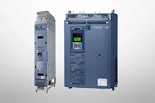
Basic type(Three-phase 200V)
Item |
Specifications |
Type (FRN□□□□G2S-2G) |
0003 |
0005 |
0008 |
0011 |
0018 |
0032 |
0046 |
0059 |
0075 |
0088 |
0115 |
0146 |
0180 |
0215 |
0288 |
0346 |
0432 |
Standard
applicable
motor (note1) |
kW |
HHD |
0.4 |
0.75 |
1.5 |
2.2 |
3.7 |
5.5 |
7.5 |
11 |
15 |
18.5 |
22 |
30 |
37 |
45 |
55 |
75 |
90 |
HND |
- |
7.5 |
11 |
15 |
18.5 |
22 |
30 |
37 |
45 |
55 |
75 |
90 |
110 |
HP |
HHD |
1/2 |
1 |
2 |
3 |
5 |
7.5 |
10 |
15 |
20 |
25 |
30 |
40 |
50 |
60 |
75 |
100 |
125 |
HND |
- |
10 |
15 |
20 |
25 |
30 |
40 |
50 |
60 |
75 |
100 |
125 |
150 |
Output
ratings |
Rated capacity
[kVA]
(note2) |
HHD |
1.1 |
1.9 |
3 |
4.1 |
6.8 |
10 |
14 |
18 |
24 |
28 |
34 |
45 |
55 |
68 |
81 |
109 |
131 |
HND |
- |
12 |
17 |
22 |
28 |
33 |
43 |
55 |
68 |
81 |
109 |
131 |
164 |
Rated current [A]
(at Ta=50°C
(122°F)) |
HHD |
3 |
5 |
8 |
11 |
18 |
27 |
37 |
49 |
63 |
76 |
90 |
119 |
146 |
180 |
215 |
288 |
346 |
HND |
- |
31.8 |
46.2 |
59.4 |
74.8 |
88 |
115 |
146 |
180 |
215 |
288 |
346 |
432 |
Rated
voltage[V]
(note 3) |
Three-phase 200 to 240 V (with AVR function) |
Three-phase 200 to 230 V (with AVR function) |
Overload current
rating [A]
(permissible
overload time) |
HHD |
150% for 1 minute, 200% for 3 seconds |
HND |
120% for 1 minute |
Ambient
temperature |
HHD |
-10 to +55 °C [14 to 131 °F] (current derating necessary in +50 to +55 °C [122 to 131 °F] range) |
HND |
-10 to +55 °C [14 to 131 °F] (current derating necessary in +50 to +55 °C [122 to 131 °F] range) |
Rated
frequency [Hz] |
50/60 Hz |
Input ratings |
Voltage, frequency |
Three-phase 200 to 240 V, 50/60 Hz |
Three-phase 200 to 230 V, 50/60 Hz |
Voltage,
frequency
fluctuation |
Voltage: +10 to -15% (interphase unbalance ratio: 2% or less) (note5), Frequency: +5 to -5 % |
Rated
current [A]
(note6) |
With
DCR |
HHD |
1.6 |
3.2 |
6.1 |
8.9 |
15 |
21.1 |
28.8 |
42.2 |
57.6 |
71 |
84.4 |
114 |
138 |
167 |
203 |
282 |
334 |
HND |
- |
28.8 |
42.2 |
57.6 |
71 |
84.4 |
114 |
138 |
167 |
203 |
282 |
334 |
410 |
Without DCR |
HHD |
3.1 |
5.3 |
9.5 |
13.2 |
22.2 |
31.5 |
42.7 |
60.7 |
80.1 |
97 |
112 |
151 |
185 |
225 |
270 |
- |
- |
HND |
- |
42.7 |
60.7 |
80.1 |
97 |
112 |
151 |
185 |
225 |
270 |
- |
- |
- |
Required
power supply
capacity
(with DCR) [kVA]
(note7) |
HHD |
0.6 |
1.2 |
2.2 |
3.1 |
5.2 |
7.4 |
10 |
15 |
20 |
25 |
30 |
40 |
48 |
58 |
71 |
98 |
116 |
HND |
- |
10 |
15 |
20 |
25 |
30 |
40 |
48 |
58 |
71 |
98 |
116 |
143 |
Auxiliary
control
power supply
voltage |
- |
Single-phase 200 to 240 V, 50/60 Hz |
Single-phase 200 to 230 V, 50/60 Hz |
Braking |
Torque [%]
(note8) |
HHD |
150 |
100 |
20 |
10 to 15 |
HND |
- |
70 |
15 |
7 to 12 |
Braking
transistor |
Built-in |
Option |
Minimum
connectable
resistance
value [Ω] |
100 |
40 |
24 |
16 |
12 |
8 |
6 |
4 |
2.5 |
2.25 |
2 |
1.6 |
- |
Built-in
braking
resistor [Ω] |
|
100 |
40 |
20 |
Option |
Time [s] |
HHD |
5 |
- |
HND |
- |
3.7 |
3.4 |
- |
%ED |
HHD |
5 |
3 |
5 |
3 |
2 |
3 |
2 |
- |
HND |
- |
2.2 |
1.4 |
- |
DC reactor (DCR) |
HHD |
Option |
Option (note9) |
HND |
Option |
Option (note9) |
Protective
construction
(IEC 60529) |
IP20 enclosed type, UL open type |
IP00 open type, UL open type
IP55 at external side when external
cooling installed |
Cooling system |
Natural cooling |
Fan cooling |
Weight [kg(lbs)] |
1.7
(3.6) |
1.9
(4.2) |
2.6
(5.7) |
2.9
(6.3) |
2.9
(6.4) |
5.8
(13) |
6.2
(14) |
5.7
(13) |
11
(23) |
11
(24) |
12
(25) |
23
(51) |
31
(68) |
40
(88) |
42
(93) |
60
(132) |
97
(214) |
-
Note 1
-
Standard applicable motor indicates Fuji Electric 4-pole standard motors. Select a motor not only based on inverter output (kW), but also so that the output rated current is greater than the motor rated current.
-
Note 2
-
The rated capacity indicates 220 V for the 200 V series, and 440 V for the 400 V series.
-
Note 3
-
It is not possible to output a voltage higher than the power supply voltage.
-
Note 5
-
Interphase unbalance ratio [%] = (Max. voltage [V] - min. voltage [V]/Three-phase average voltage [V] x 67 (see IEC/EN 61800-3).
If using the motor with an unbalance ratio of 2 to 3%, use an AC reactor (ACR: option).
-
Note 6
-
This indicates the estimated value if the power supply capacity is 500 kVA (10 times inverter capacity if inverter capacity exceeds 50 kVA), and the motor is connected to a power supply of %X = 5%.
-
Note 7
-
This indicates the capacity when the motor is equipped with a DC reactor (DCR).
-
Note 8
-
This is the average braking torque when performing individual operation. (This will vary based on the motor efficiency.)
-
Note 9
-
When applying a motor of 75kW or more, be sure to use a DC reactor (option).
Basic type(Three-phase 200V)
Item |
Specifications |
Type (FRN□□□□G2S-2G) |
0003 |
0005 |
0008 |
0011 |
0018 |
0032 |
0046 |
0059 |
0075 |
0088 |
0115 |
0146 |
0180 |
0215 |
0288 |
0346 |
0432 |
Standard
applicable
motor (note1) |
kW |
HHD |
0.4 |
0.75 |
1.5 |
2.2 |
3.7 |
5.5 |
7.5 |
11 |
15 |
18.5 |
22 |
30 |
37 |
45 |
55 |
75 |
90 |
HND |
- |
7.5 |
11 |
15 |
18.5 |
22 |
30 |
37 |
45 |
55 |
75 |
90 |
110 |
HP |
HHD |
1/2 |
1 |
2 |
3 |
5 |
7.5 |
10 |
15 |
20 |
25 |
30 |
40 |
50 |
60 |
75 |
100 |
125 |
HND |
- |
10 |
15 |
20 |
25 |
30 |
40 |
50 |
60 |
75 |
100 |
125 |
150 |
Output
ratings |
Rated capacity
[kVA]
(note2) |
HHD |
1.1 |
1.9 |
3 |
4.1 |
6.8 |
10 |
14 |
18 |
24 |
28 |
34 |
45 |
55 |
68 |
81 |
109 |
131 |
HND |
- |
12 |
17 |
22 |
28 |
33 |
43 |
55 |
68 |
81 |
109 |
131 |
164 |
Rated current [A]
(at Ta=50°C
(122°F)) |
HHD |
3 |
5 |
8 |
11 |
18 |
27 |
37 |
49 |
63 |
76 |
90 |
119 |
146 |
180 |
215 |
288 |
346 |
HND |
- |
31.8 |
46.2 |
59.4 |
74.8 |
88 |
115 |
146 |
180 |
215 |
288 |
346 |
432 |
Rated
voltage[V]
(note3) |
Three-phase 200 to 240 V (with AVR function) |
Three-phase 200 to 230 V (with AVR function) |
Overload current
rating [A]
(permissible
overload time) |
HHD |
150% for 1 minute, 200% for 3 seconds |
HND |
120% for 1 minute |
Ambient
temperature |
HHD |
-10 to +55 °C [14 to 131 °F] (current derating necessary in +50 to +55 °C [122 to 131 °F] range) |
HND |
-10 to +55 °C [14 to 131 °F] (current derating necessary in +50 to +55 °C [122 to 131 °F] range) |
Rated
frequency [Hz] |
50/60 Hz |
Input ratings |
Voltage, frequency |
Three-phase 200 to 240 V, 50/60 Hz |
Three-phase 200 to 230 V, 50/60 Hz |
Voltage,
frequency
fluctuation |
Voltage: +10 to -15% (interphase unbalance ratio: 2% or less) (note5), Frequency: +5 to -5 % |
Rated
current [A]
(note6) |
With
DCR |
HHD |
1.6 |
3.2 |
6.1 |
8.9 |
15 |
21.1 |
28.8 |
42.2 |
57.6 |
71 |
84.4 |
114 |
138 |
167 |
203 |
282 |
334 |
HND |
- |
28.8 |
42.2 |
57.6 |
71 |
84.4 |
114 |
138 |
167 |
203 |
282 |
334 |
410 |
Without DCR |
HHD |
3.1 |
5.3 |
9.5 |
13.2 |
22.2 |
31.5 |
42.7 |
60.7 |
80.1 |
97 |
112 |
151 |
185 |
225 |
270 |
- |
- |
HND |
- |
42.7 |
60.7 |
80.1 |
97 |
112 |
151 |
185 |
225 |
270 |
- |
- |
- |
Required
power supply
capacity
(with DCR) [kVA]
(note7) |
HHD |
0.6 |
1.2 |
2.2 |
3.1 |
5.2 |
7.4 |
10 |
15 |
20 |
25 |
30 |
40 |
48 |
58 |
71 |
98 |
116 |
HND |
- |
10 |
15 |
20 |
25 |
30 |
40 |
48 |
58 |
71 |
98 |
116 |
143 |
Auxiliary
control
power supply
voltage |
- |
Single-phase 200 to 240 V, 50/60 Hz |
Single-phase 200 to 230 V, 50/60 Hz |
Braking |
Torque [%]
(note8) |
HHD |
150 |
100 |
20 |
10 to 15 |
HND |
- |
70 |
15 |
7 to 12 |
Braking
transistor |
Built-in |
Option |
Minimum
connectable
resistance
value [Ω] |
100 |
40 |
24 |
16 |
12 |
8 |
6 |
4 |
2.5 |
2.25 |
2 |
1.6 |
- |
Built-in
braking
resistor [Ω] |
|
100 |
40 |
20 |
Option |
Time [s] |
HHD |
5 |
- |
HND |
- |
3.7 |
3.4 |
- |
%ED |
HHD |
5 |
3 |
5 |
3 |
2 |
3 |
2 |
- |
HND |
- |
2.2 |
1.4 |
- |
DC reactor (DCR) |
HHD |
Option |
Option (note9) |
HND |
Option |
Option (note9) |
Protective
construction
(IEC 60529) |
IP20 enclosed type, UL open type |
IP00 open type, UL open type
IP55 at external side when external
cooling installed |
Cooling system |
Natural cooling |
Fan cooling |
Weight [kg(lbs)] |
1.7
(3.6) |
1.9
(4.2) |
2.6
(5.7) |
2.9
(6.3) |
2.9
(6.4) |
5.8
(13) |
6.2
(14) |
5.7
(13) |
11
(23) |
11
(24) |
12
(25) |
23
(51) |
31
(68) |
40
(88) |
42
(93) |
60
(132) |
97
(214) |
-
Note 1
-
Standard applicable motor indicates Fuji Electric 4-pole standard motors. Select a motor not only based on inverter output (kW), but also so that the output rated current is greater than the motor rated current.
-
Note 2
-
The rated capacity indicates 220 V for the 200 V series, and 440 V for the 400 V series.
-
Note 3
-
It is not possible to output a voltage higher than the power supply voltage.
-
Note 5
-
These values are calculated on assumption that the inverter is connected to a power supply with a capacity of 500 kVA (or 10 times the inverter capacity when the inverter capacity exceeds 50 kVA) and %X is 5%.
-
Note 6
-
This indicates the estimated value if the power supply capacity is 500 kVA (10 times inverter capacity if inverter capacity exceeds 50 kVA), and the motor is connected to a power supply of %X = 5%.
-
Note 7
-
This indicates the capacity when the motor is equipped with a DC reactor (DCR).
-
Note 8
-
This is the average braking torque when performing individual operation. (This will vary based on the motor efficiency.)
-
Note 9
-
When applying a motor of 75kW or more, be sure to use a DC reactor (option).
Basic type(Three-phase 200V)(Three-phase 200V)
Item |
Specifications |
Type (FRN□□□G2S-2J) |
HHD |
0.4 |
0.75 |
1.5 |
2.2 |
3.7 |
5.5 |
7.5 |
11 |
15 |
18.5 |
22 |
30 |
37 |
45 |
55 |
75 |
90 |
HND |
ー |
5.5 |
7.5 |
11 |
15 |
18.5 |
22 |
30 |
37 |
45 |
55 |
75 |
90 |
Nominal applied motor [kW (HP)] (Note1) |
HHD |
0.4 |
0.75 |
1.5 |
2.2 |
3.7 |
5.5 |
7.5 |
11 |
15 |
18.5 |
22 |
30 |
37 |
45 |
55 |
75 |
90 |
HND |
ー |
7.5 |
11 |
15 |
18.5 |
22 |
30 |
37 |
45 |
55 |
75 |
90 |
110 |
Output ratings |
Rated capacity [kVA] (Note2) |
HHD |
1.1 |
1.9 |
3 |
4.1 |
6.8 |
10 |
14 |
18 |
24 |
28 |
34 |
45 |
55 |
68 |
81 |
109 |
131 |
HND |
ー |
12 |
17 |
22 |
28 |
33 |
43 |
55 |
68 |
81 |
109 |
131 |
164 |
Rated voltage [V] (Note3) |
Three-phase 200 to 240 (with AVR function) |
Three-phase 200 to 230 (with AVR function) |
Rated current [A] |
HHD |
3 |
5 |
8 |
11 |
18 |
27 |
37 |
49 |
63 |
76 |
90 |
119 |
146 |
180 |
215 |
288 |
346 |
HND |
ー |
31.8 |
46.2 |
59.4 |
74.8 |
88 |
115 |
146 |
180 |
215 |
288 |
346 |
432 |
Overload capacity |
HHD |
150%-1min, 200%-3.0s |
HND |
ー |
120%-1min |
Rated frequency [Hz] |
HHD |
50, 60 |
HND |
ー |
50, 60 |
Input ratings |
Main circuit power: Phases, voltage, frequency |
Three-phase 200 to 240V, 50/60Hz |
Three-phase 200 to 230V, 50/60Hz |
Auxiliary control power input: Phases, voltage, frequency |
ー |
Single-phase 200 to 240V, 50/60Hz |
Single-phase 200 to 230V, 50/60Hz |
Voltage, frequency variations |
HHD |
Voltage:(10 to -15% (Voltage unbalance:2% or less (Note4)) Frequency:+5 to -5% |
HND |
ー |
Voltage:(10 to -15% (Voltage unbalance:2% or less (Note4)) Frequency:+5 to -5% |
Rated current [A] (Note5) |
with DCR |
HHD |
1.6 |
3.2 |
6.1 |
8.9 |
15 |
21.1 |
28.8 |
42.2 |
57.6 |
71 |
84.4 |
114 |
138 |
167 |
203 |
282 |
334 |
with DCR |
HND |
ー |
28.8 |
42.2 |
57.6 |
71 |
84.4 |
114 |
138 |
167 |
203 |
282 |
334 |
410 |
without DCR |
HHD |
3.1 |
5.3 |
9.5 |
13.2 |
22.2 |
31.5 |
42.7 |
60.7 |
80.1 |
97 |
112 |
151 |
185 |
225 |
270 |
- |
- |
without DCR |
HND |
ー |
42.7 |
60.7 |
80.1 |
97 |
112 |
151 |
185 |
225 |
270 |
- |
- |
- |
Required power supply capacity [kVA] (Note6) |
with DCR |
HHD |
0.6 |
1.2 |
2.2 |
3.1 |
5.2 |
7.4 |
10 |
15 |
20 |
25 |
30 |
40 |
48 |
58 |
71 |
98 |
116 |
HND |
ー |
10 |
15 |
20 |
25 |
30 |
40 |
48 |
58 |
71 |
98 |
116 |
143 |
Braking |
Torque [%] (Note7) |
HHD |
150 |
100 |
20 |
10 to 15 |
HND |
ー |
70 |
15 |
7 to 12 |
Braking transistor |
Built-in as standard |
Option |
Min. ohmic value [Ω] |
100 |
40 |
24 |
16 |
12 |
8 |
6 |
4 |
2.5 |
2.25 |
2 |
1.6 |
ー |
Built-in braking resistance [Ω] |
|
100 |
40 |
20 |
Option |
Braking time[s] |
HHD |
5 |
ー |
HND |
ー |
3.7 |
3.4 |
ー |
%ED |
HHD |
5 |
3 |
5 |
3 |
2 |
3 |
2 |
ー |
HND |
ー |
2.2 |
1.4 |
ー |
DC injection braking |
HHD |
Starting frequency: 0.0 to 60.0Hz, Braking time: 0.0 to 30.0s, Braking level: 0 to 100% |
HND |
ー |
Starting frequency: 0.0 to 60.0Hz, Braking time: 0.0 to 30.0s, Braking level: 0 to 80% |
DC reactor (DCR) |
HHD |
Option |
Option(Note8) |
HND |
Option |
Option(Note8) |
Applicable safety standards (Planned) |
UL61800-5-1,UL 61800-5-2 SIL3 (Functional Safety : STO),ISO 13849-1 Cat.3 / PL:e,C22.2 No.274-17,IEC/EN 61800-5-1, EN 61800-5-2 SIL3 (Functional Safety : STO),EN ISO 13849-1 Cat.3 / PL:e, EN 60204-1 stop category 0, EN 62061 SIL3, SEMI F47-0706 |
Enclosure (IEC60529) |
IP20 closed type, UL open type (Planned) |
IP00 open type, UL open type
IP55 at external side when external cooling installed |
Cooling method |
Natural cooling |
Fan cooling |
Weight/Mass [kg (lb)] |
1.7 |
1.9 |
2.6 |
2.9 |
2.9 |
5.8 |
6.2 |
5.7 |
11 |
11 |
12 |
25 |
31 |
40 |
42 |
60 |
97 |
-
Note 1
-
Fuji's 4-pole standard motor When selecting an inverter, in addition to considering the kWs of the inverter, make sure that the output current rating is larger than the motor current rating.
-
Note 2
-
Rated capacity is calculated by assuming the rated output voltage as 220 V for 200 V series and 440 V for 400 V series.
-
Note 3
-
Output voltage cannot exceed the power supply voltage.
-
Note 4
-
Voltage unbalance(%) =Max. voltage (V) - Min. voltage (V) / Three-phase average voltage (V) ×67 (IEC 61800-3) If this value is 2 to 3%, use an optional AC reactor (ACR).
-
Note 5
-
These values are calculated on assumption that the inverter is connected to a power supply with a capacity of 500 kVA (or 10 times the inverter capacity when the inverter capacity exceeds 50 kVA) and %X is 5%.
-
Note 6
-
Required when a DC reactor (DCR) is used.
-
Note 7
-
This is the average braking torque when performing individual operation. (This will vary based on the motor efficiency.)
-
Note 8
-
When using a motor with a rating of 75 kW or more, be sure to use a DC reactor (option).
EMC filter built-in type(Three-phase 200V)
Item |
Specifications |
Type (FRN□□□G2E-2J) |
HHD |
0.4 |
0.75 |
1.5 |
2.2 |
3.7 |
5.5 |
7.5 |
11 |
15 |
18.5 |
22 |
30 |
37 |
45 |
55 |
75 |
90 |
HND |
ー |
5.5 |
7.5 |
11 |
15 |
18.5 |
22 |
30 |
37 |
45 |
55 |
75 |
90 |
Nominal applied motor [kW (HP)] (Note1) |
HHD |
0.4 |
0.75 |
1.5 |
2.2 |
3.7 |
5.5 |
7.5 |
11 |
15 |
18.5 |
22 |
30 |
37 |
45 |
55 |
75 |
90 |
HND |
ー |
7.5 |
11 |
15 |
18.5 |
22 |
30 |
37 |
45 |
55 |
75 |
90 |
110 |
Output ratings |
Rated capacity [kVA] (Note2) |
HHD |
1.1 |
1.9 |
3 |
4.1 |
6.8 |
10 |
14 |
18 |
24 |
28 |
34 |
45 |
55 |
68 |
81 |
109 |
131 |
HND |
ー |
12 |
17 |
22 |
28 |
33 |
43 |
55 |
68 |
81 |
109 |
131 |
164 |
Rated voltage [V] (Note3) |
Three-phase 200 to 240 (with AVR function) |
Three-phase 200 to 230 (with AVR function) |
Rated current [A] |
HHD |
3 |
5 |
8 |
11 |
18 |
27 |
37 |
49 |
63 |
76 |
90 |
119 |
146 |
180 |
215 |
288 |
346 |
HND |
ー |
318 |
46.2 |
59.4 |
74.8 |
88 |
115 |
146 |
180 |
215 |
288 |
346 |
432 |
Overload capacity |
HHD |
150%-1min, 200%-3.0s |
HND |
ー |
120%-1min |
Rated frequency [Hz] |
50, 60 |
Input ratings |
Main circuit power: Phases, voltage, frequency |
Three-phase 200 to 240V, 50/60Hz |
Three-phase 200 to 230V, 50/60Hz |
Auxiliary control power input: Phases, voltage, frequency |
ー |
Single-phase 200 to 240V, 50/60Hz |
Single-phase 200 to 230V, 50/60Hz |
Voltage, frequency variations |
Voltage:(10 to -15% (Voltage unbalance:2% or less (Note4)) Frequency:+5 to -5% |
Rated current [A] (Note5) |
with DCR |
HHD |
1.6 |
3.2 |
6.1 |
8.9 |
15 |
21.1 |
28.8 |
42.2 |
57.6 |
71 |
84.4 |
114 |
138 |
167 |
203 |
282 |
334 |
HND |
ー |
28.8 |
42.2 |
57.6 |
71 |
84.4 |
114 |
138 |
167 |
203 |
282 |
334 |
410 |
without DCR |
HHD |
3.1 |
5.3 |
9.5 |
13.2 |
22.2 |
31.5 |
42.7 |
60.7 |
80.1 |
97 |
112 |
151 |
185 |
225 |
270 |
ー |
ー |
HND |
ー |
42.7 |
60.7 |
80.1 |
97 |
112 |
151 |
185 |
225 |
270 |
ー |
ー |
ー |
Required power supply capacity [kVA] (Note6) |
with DCR |
HHD |
0.6 |
1.2 |
2.2 |
3.1 |
5.2 |
7.4 |
10 |
15 |
20 |
25 |
30 |
40 |
48 |
58 |
71 |
98 |
116 |
HND |
ー |
10 |
15 |
20 |
25 |
30 |
40 |
48 |
58 |
71 |
98 |
116 |
143 |
Braking |
Torque [%] (Note7) |
HHD |
150 |
100 |
20 |
10 to 15 |
HND |
ー |
70 |
15 |
7 to 12 |
Braking transistor |
Built-in as standard |
Option |
Min. ohmic value [Ω] |
100 |
40 |
24 |
16 |
12 |
8 |
6 |
4 |
2.5 |
2.25 |
2 |
1.6 |
ー |
Built-in braking resistance [Ω] |
|
100 |
40 |
20 |
Option |
Braking time[s] |
HHD |
5 |
ー |
HND |
ー |
3.7 |
3.4 |
ー |
%ED |
HHD |
5 |
3 |
5 |
3 |
2 |
3 |
2 |
ー |
HND |
ー |
2.2 |
1.4 |
ー |
DC injection braking |
HHD |
Starting frequency: 0.0 to 60.0Hz, Braking time: 0.0 to 30.0s, Braking level: 0 to 100% |
HND |
ー |
Starting frequency: 0.0 to 60.0Hz, Braking time: 0.0 to 30.0s, Braking level: 0 to 80% |
EMC Filter |
Conforming EMC standards Emission, Immunity: Category C3 (2nd Env. (IEC61800-3)) |
DC reactor (DCR) |
HHD |
Option |
Option (Note8) |
HND |
ー |
Option |
Option (Note8) |
Applicable safety standards (Planned) |
UL61800-5-1,UL 61800-5-2 SIL3 (Functional Safety : STO),ISO 13849-1 Cat.3 / PL:e,C22.2 No.274-17,IEC/EN 61800-5-1, EN 61800-5-2 SIL3 (Functional Safety : STO),EN ISO 13849-1 Cat.3 / PL:e, EN 60204-1 stop category 0, EN 62061 SIL3, SEMI F47-0706 |
Enclosure (IEC60529) |
IP20 closed type, UL open type |
IP00 open type, UL open type
IP55 at external side when external cooling installed |
Cooling method |
Natural cooling |
Fan cooling |
Weight/Mass [kg (lb)] |
1.8 |
2 |
2.8 |
3.1 |
3.1 |
6.4 |
6.8 |
6.4 |
12 |
12 |
12 |
25 |
31 |
40 |
42 |
60 |
97 |
-
Note 1
-
Fuji's 4-pole standard motor When selecting an inverter, in addition to considering the kWs of the inverter, make sure that the output current rating is larger than the motor current rating.
-
Note 2
-
Rated capacity is calculated by assuming the rated output voltage as 220 V for 200 V series and 440 V for 400 V series.
-
Note 3
-
Output voltage cannot exceed the power supply voltage.
-
Note 4
-
Voltage unbalance(%) =Max. voltage (V) - Min. voltage (V) / Three-phase average voltage (V) ×67 (IEC 61800-3) If this value is 2 to 3%, use an optional AC reactor (ACR).
-
Note 5
-
These values are calculated on assumption that the inverter is connected to a power supply with a capacity of 500 kVA (or 10 times the inverter capacity when the inverter capacity exceeds 50 kVA) and %X is 5%.
-
Note 6
-
Required when a DC reactor (DCR) is used.
-
Note 7
-
This is the average braking torque when performing individual operation. (This will vary based on the motor efficiency.)
-
Note 8
-
When using a motor with a rating of 75 kW or more, be sure to use a DC reactor (option).
Zero-phase built-in reactor type(Three-phase 200V)
High carrier frequency Normal Duty
Item |
Specifications |
Type (FRN□□□G2P-2J) |
1.5 |
2.2 |
3.7 |
5.5 |
7.5 |
11 |
15 |
18.5 |
22 |
30 |
37 |
45 |
55 |
75 |
Nominal applied motor [kW (HP)] (Note1) |
1.5 |
2.2 |
3.7 |
5.5 |
7.5 |
11 |
15 |
18.5 |
22 |
30 |
37 |
45 |
55 |
75 |
Output ratings |
Rated capacity [kVA] (Note2) |
2.9 |
4 |
6.3 |
9 |
12 |
17 |
22 |
28 |
33 |
43 |
55 |
71 |
80 |
109 |
Rated voltage [V] (Note3) |
Three-phase 200 to 240 (with AVR function) |
Three-phase 200 to 230 (with AVR function) |
Rated current [A] |
7.7 |
10.6 |
16.7 |
23.8 |
31.8 |
46.2 |
59.4 |
74.8 |
88 |
115 |
146 |
187 |
212 |
288 |
Overload capacity |
120%-1min |
Rated frequency [Hz] |
50, 60 |
Input ratings |
Main circuit power: Phases, voltage, frequency |
Three-phase 200 to 240V, 50/60Hz |
Three-phase 200 to 230V, 50/60Hz |
Auxiliary control power input: Phases, voltage, frequency |
Single-phase 200 to 240V, 50/60Hz |
Single-phase 200 to 230V, 50/60Hz |
Voltage, frequency variations |
Voltage:(10 to -15% (Voltage unbalance:2% or less (Note4)) Frequency:+5 to -5% |
Rated current [A] (Note5) |
with DCR |
6.1 |
8.9 |
15 |
21.1 |
28.8 |
42.2 |
57.6 |
71 |
84.4 |
114 |
138 |
167 |
203 |
282 |
without DCR |
9.5 |
13.2 |
22.2 |
31.5 |
42.7 |
60.7 |
80.1 |
97 |
112 |
151 |
185 |
225 |
270 |
ー |
Required power supply capacity [kVA] (Note6) |
with DCR |
2.2 |
3.1 |
5.2 |
7.4 |
10 |
15 |
20 |
25 |
30 |
40 |
48 |
58 |
71 |
98 |
Braking |
Torque [%] (Note7) |
100 |
70 |
15 |
7 to 12 |
Braking transistor |
Built-in as standard |
Min. ohmic value [Ω] |
40 |
24 |
16 |
12 |
8 |
6 |
4 |
2.5 |
2.25 |
1.6 |
Built-in braking resistance [Ω] |
|
40 |
20 |
Option |
Braking time[s] |
5 |
5 |
5 |
3.4 |
3.7 |
3.4 |
ー |
%ED |
5 |
3 |
2 |
1.3 |
2.2 |
1.4 |
ー |
DC injection braking |
Starting frequency: 0.0 to 60.0Hz, Braking time: 0.0 to 30.0s, Braking level: 0 to 80% |
Zero-phase reactor |
Built-in as standard |
DC reactor (DCR) |
Option |
Option (Note8) |
Applicable safety standards (Planned) |
UL61800-5-1, C22.2 No.274-17 |
Enclosure (IEC60529) |
IP20 closed type, UL open type (Planned) |
IP00 open type, UL open type
IP55 at external side when external cooling installed |
Cooling method |
Natural cooling |
Fan cooling |
Weight/Mass [kg (lb)] |
2.7 |
3 |
3.1 |
3.1 |
6.1 |
6.5 |
6 |
11 |
11 |
12 |
25 |
34 |
34 |
45 |
-
Note 1
-
Fuji's 4-pole standard motor When selecting an inverter, in addition to considering the kWs of the inverter, make sure that the output current rating is larger than the motor current rating.
-
Note 2
-
Rated capacity is calculated by assuming the rated output voltage as 220 V for 200 V series and 440 V for 400 V series.
-
Note 3
-
Output voltage cannot exceed the power supply voltage.
-
Note 4
-
Voltage unbalance(%) =Max. voltage (V) - Min. voltage (V) / Three-phase average voltage (V) ×67 (IEC 61800-3) If this value is 2 to 3%, use an optional AC reactor (ACR).
-
Note 5
-
These values are calculated on assumption that the inverter is connected to a power supply with a capacity of 500 kVA (or 10 times the inverter capacity when the inverter capacity exceeds 50 kVA) and %X is 5%.
-
Note 6
-
Required when a DC reactor (DCR) is used.
-
Note 7
-
This is the average braking torque when performing individual operation. (This will vary based on the motor efficiency.)
-
Note 8
-
When using a motor with a rating of 75 kW or more, be sure to use a DC reactor (option).
DCR built-in type(Three-phase 200V)
Item |
Specifications |
Type (FRN□□□G2H-2J) |
30 |
37 |
45 |
55 |
Nominal applied motor [kW (HP)] (Note1) |
HHD |
30 |
37 |
45 |
55 |
HND |
37 |
45 |
55 |
75 |
Output ratings |
Rated capacity [kVA] (Note2) |
HHD |
45 |
55 |
68 |
81 |
HND |
55 |
68 |
81 |
100 |
Rated voltage [V] (Note3) |
Three-phase 200 to 230 (with AVR function) |
Rated current [A] |
HHD |
119 |
146 |
180 |
215 |
HND |
146 |
180 |
215 |
288 |
Overload capacity |
HHD |
150%-1min, 200%-3.0s |
HND |
120%-1min |
Rated frequency [Hz] |
50, 60 |
Input ratings |
Main circuit power: Phases, voltage, frequency |
Three-phase 200 to 230V, 50/60Hz |
Auxiliary control power input: Phases, voltage, frequency |
Single-phase 200 to 230V, 50/60Hz |
Voltage, frequency variations |
Voltage:(10 to -15% (Voltage unbalance:2% or less (Note4)) Frequency:+5 to -5% |
Rated current [A] (Note5) |
HHD |
122 |
152 |
186 |
223 |
HND |
145 |
179 |
215 |
284 |
Required power supply capacity [kVA] (Note6) |
HHD |
43 |
53 |
65 |
78 |
HND |
51 |
63 |
75 |
99 |
Braking |
Torque [%] (Note7) |
HHD |
10 to 15 |
HND |
7 to 12 |
Braking transistor |
Built-in as standard |
Min. ohmic value [Ω] |
2.5 |
2.25 |
2 |
1.6 |
DC injection braking |
Starting frequency: 0.0 to 60.0Hz, Braking time: 0.0 to 30.0s, Braking level: 0 to 100% |
DC reactor (DCR) |
Built-in (Power factor of 80% or higher (Note9)) |
Applicable safety standards (Planned) |
UL61800-5-1,UL 61800-5-2 SIL3 (Functional Safety : STO), ISO 13849-1 Cat.3 / PL:e,C22.2 No.274-17,IEC/EN 61800-5-1,
EN 61800-5-2 SIL3 (Functional Safety : STO),EN ISO 13849-1 Cat.3 / PL:e,
EN 60204-1 stop category 0, EN 62061 SIL3, SEMI F47-0706 |
Enclosure (IEC60529) |
IP00 open type, UL open type
IP55 at external side when external cooling installed |
Cooling method |
Fan cooling |
Weight/Mass [kg (lb)] |
29 |
38 |
48 |
51 |
-
Note 1
-
Fuji's 4-pole standard motor When selecting an inverter, in addition to considering the kWs of the inverter, make sure that the output current rating is larger than the motor current rating.
-
Note 2
-
Rated capacity is calculated by assuming the rated output voltage as 220 V for 200 V series and 440 V for 400 V series.
-
Note 3
-
Output voltage cannot exceed the power supply voltage.
-
Note 4
-
Voltage unbalance(%) =Max. voltage (V) - Min. voltage (V) / Three-phase average voltage (V) ×67 (IEC 61800-3) If this value is 2 to 3%, use an optional AC reactor (ACR).
-
Note 5
-
These values are calculated on assumption that the inverter is connected to a power supply with a capacity of 500 kVA (or 10 times the inverter capacity when the inverter capacity exceeds 50 kVA) and %X is 5%.
-
Note 6
-
Required when a DC reactor (DCR) is used.
-
Note 7
-
This is the average braking torque when performing individual operation. (This will vary based on the motor efficiency.)
-
Note 9
-
This is the value at the rated output when the voltage unbalance of the power supply is 0%
Basic type(Three-phase 200V)
Item |
Specifications |
Type (FRN□□□G2S-2J) |
HHD |
0.4 |
0.75 |
1.5 |
2.2 |
3.7 |
5.5 |
7.5 |
11 |
15 |
18.5 |
22 |
30 |
37 |
45 |
55 |
75 |
90 |
HND |
ー |
5.5 |
7.5 |
11 |
15 |
18.5 |
22 |
30 |
37 |
45 |
55 |
75 |
90 |
Nominal applied motor [kW (HP)] (Note1) |
HHD |
0.4 |
0.75 |
1.5 |
2.2 |
3.7 |
5.5 |
7.5 |
11 |
15 |
18.5 |
22 |
30 |
37 |
45 |
55 |
75 |
90 |
HND |
ー |
7.5 |
11 |
15 |
18.5 |
22 |
30 |
37 |
45 |
55 |
75 |
90 |
110 |
Output ratings |
Rated capacity [kVA] (Note2) |
HHD |
1.1 |
1.9 |
3 |
4.1 |
6.8 |
10 |
14 |
18 |
24 |
28 |
34 |
45 |
55 |
68 |
81 |
109 |
131 |
HND |
ー |
12 |
17 |
22 |
28 |
33 |
43 |
55 |
68 |
81 |
109 |
131 |
164 |
Rated voltage [V] (Note3) |
Three-phase 200 to 240 (with AVR function) |
Three-phase 200 to 230 (with AVR function) |
Rated current [A] |
HHD |
3 |
5 |
8 |
11 |
18 |
27 |
37 |
49 |
63 |
76 |
90 |
119 |
146 |
180 |
215 |
288 |
346 |
HND |
ー |
31.8 |
46.2 |
59.4 |
74.8 |
88 |
115 |
146 |
180 |
215 |
288 |
346 |
432 |
Overload capacity |
HHD |
150%-1min, 200%-3.0s |
HND |
ー |
120%-1min |
Rated frequency [Hz] |
HHD |
50, 60 |
HND |
ー |
50, 60 |
Input ratings |
Main circuit power: Phases, voltage, frequency |
Three-phase 200 to 240V, 50/60Hz |
Three-phase 200 to 230V, 50/60Hz |
Auxiliary control power input: Phases, voltage, frequency |
ー |
Single-phase 200 to 240V, 50/60Hz |
Single-phase 200 to 230V, 50/60Hz |
Voltage, frequency variations |
HHD |
Voltage:(10 to -15% (Voltage unbalance:2% or less (Note4)) Frequency:+5 to -5% |
HND |
ー |
Voltage:(10 to -15% (Voltage unbalance:2% or less (Note4)) Frequency:+5 to -5% |
Rated current [A] (Note5) |
with DCR |
HHD |
1.6 |
3.2 |
6.1 |
8.9 |
15 |
21.1 |
28.8 |
42.2 |
57.6 |
71 |
84.4 |
114 |
138 |
167 |
203 |
282 |
334 |
with DCR |
HND |
ー |
28.8 |
42.2 |
57.6 |
71 |
84.4 |
114 |
138 |
167 |
203 |
282 |
334 |
410 |
without DCR |
HHD |
3.1 |
5.3 |
9.5 |
13.2 |
22.2 |
31.5 |
42.7 |
60.7 |
80.1 |
97 |
112 |
151 |
185 |
225 |
270 |
- |
- |
without DCR |
HND |
ー |
42.7 |
60.7 |
80.1 |
97 |
112 |
151 |
185 |
225 |
270 |
- |
- |
- |
Required power supply capacity [kVA] (Note6) |
with DCR |
HHD |
0.6 |
1.2 |
2.2 |
3.1 |
5.2 |
7.4 |
10 |
15 |
20 |
25 |
30 |
40 |
48 |
58 |
71 |
98 |
116 |
HND |
ー |
10 |
15 |
20 |
25 |
30 |
40 |
48 |
58 |
71 |
98 |
116 |
143 |
Braking |
Torque [%] (Note7) |
HHD |
150 |
100 |
20 |
10 to 15 |
HND |
ー |
70 |
15 |
7 to 12 |
Braking transistor |
Built-in as standard |
Option |
Min. ohmic value [Ω] |
100 |
40 |
24 |
16 |
12 |
8 |
6 |
4 |
2.5 |
2.25 |
2 |
1.6 |
ー |
Built-in braking resistance [Ω] |
|
100 |
40 |
20 |
Option |
Braking time[s] |
HHD |
5 |
ー |
HND |
ー |
3.7 |
3.4 |
ー |
%ED |
HHD |
5 |
3 |
5 |
3 |
2 |
3 |
2 |
ー |
HND |
ー |
2.2 |
1.4 |
ー |
DC injection braking |
HHD |
Starting frequency: 0.0 to 60.0Hz, Braking time: 0.0 to 30.0s, Braking level: 0 to 100% |
HND |
ー |
Starting frequency: 0.0 to 60.0Hz, Braking time: 0.0 to 30.0s, Braking level: 0 to 80% |
DC reactor (DCR) |
HHD |
Option |
Option(Note8) |
HND |
Option |
Option(Note8) |
Applicable safety standards (Planned) |
UL61800-5-1,UL 61800-5-2 SIL3 (Functional Safety : STO),ISO 13849-1 Cat.3 / PL:e,C22.2 No.274-17,IEC/EN 61800-5-1, EN 61800-5-2 SIL3 (Functional Safety : STO),EN ISO 13849-1 Cat.3 / PL:e, EN 60204-1 stop category 0, EN 62061 SIL3, SEMI F47-0706 |
Enclosure (IEC60529) |
IP20 closed type, UL open type (Planned) |
IP00 open type, UL open type
IP55 at external side when external cooling installed |
Cooling method |
Natural cooling |
Fan cooling |
Weight/Mass [kg (lb)] |
1.7 |
1.9 |
2.6 |
2.9 |
2.9 |
5.8 |
6.2 |
5.7 |
11 |
11 |
12 |
25 |
31 |
40 |
42 |
60 |
97 |
-
Note 1
-
Fuji's 4-pole standard motor When selecting an inverter, in addition to considering the kWs of the inverter, make sure that the output current rating is larger than the motor current rating.
-
Note 2
-
Rated capacity is calculated by assuming the rated output voltage as 220 V for 200 V series and 440 V for 400 V series.
-
Note 3
-
Output voltage cannot exceed the power supply voltage.
-
Note 4
-
Voltage unbalance(%) =Max. voltage (V) - Min. voltage (V) / Three-phase average voltage (V) ×67 (IEC 61800-3) If this value is 2 to 3%, use an optional AC reactor (ACR).
-
Note 5
-
These values are calculated on assumption that the inverter is connected to a power supply with a capacity of 500 kVA (or 10 times the inverter capacity when the inverter capacity exceeds 50 kVA) and %X is 5%.
-
Note 6
-
Required when a DC reactor (DCR) is used.
-
Note 7
-
This is the average braking torque when performing individual operation. (This will vary based on the motor efficiency.)
-
Note 8
-
When using a motor with a rating of 75 kW or more, be sure to use a DC reactor (option).
EMC filter built-in type(Three-phase 200V)
Item |
Specifications |
Type (FRN□□□G2E-2J) |
HHD |
0.4 |
0.75 |
1.5 |
2.2 |
3.7 |
5.5 |
7.5 |
11 |
15 |
18.5 |
22 |
30 |
37 |
45 |
55 |
75 |
90 |
HND |
ー |
5.5 |
7.5 |
11 |
15 |
18.5 |
22 |
30 |
37 |
45 |
55 |
75 |
90 |
Nominal applied motor [kW (HP)] (Note1) |
HHD |
0.4 |
0.75 |
1.5 |
2.2 |
3.7 |
5.5 |
7.5 |
11 |
15 |
18.5 |
22 |
30 |
37 |
45 |
55 |
75 |
90 |
HND |
ー |
7.5 |
11 |
15 |
18.5 |
22 |
30 |
37 |
45 |
55 |
75 |
90 |
110 |
Output ratings |
Rated capacity [kVA] (Note2) |
HHD |
1.1 |
1.9 |
3 |
4.1 |
6.8 |
10 |
14 |
18 |
24 |
28 |
34 |
45 |
55 |
68 |
81 |
109 |
131 |
HND |
ー |
12 |
17 |
22 |
28 |
33 |
43 |
55 |
68 |
81 |
109 |
131 |
164 |
Rated voltage [V] (Note3) |
Three-phase 200 to 240 (with AVR function) |
Three-phase 200 to 230 (with AVR function) |
Rated current [A] |
HHD |
3 |
5 |
8 |
11 |
18 |
27 |
37 |
49 |
63 |
76 |
90 |
119 |
146 |
180 |
215 |
288 |
346 |
HND |
ー |
318 |
46.2 |
59.4 |
74.8 |
88 |
115 |
146 |
180 |
215 |
288 |
346 |
432 |
Overload capacity |
HHD |
150%-1min, 200%-3.0s |
HND |
ー |
120%-1min |
Rated frequency [Hz] |
50, 60 |
Input ratings |
Main circuit power: Phases, voltage, frequency |
Three-phase 200 to 240V, 50/60Hz |
Three-phase 200 to 230V, 50/60Hz |
Auxiliary control power input: Phases, voltage, frequency |
ー |
Single-phase 200 to 240V, 50/60Hz |
Single-phase 200 to 230V, 50/60Hz |
Voltage, frequency variations |
Voltage:(10 to -15% (Voltage unbalance:2% or less (Note4)) Frequency:+5 to -5% |
Rated current [A] (Note5) |
with DCR |
HHD |
1.6 |
3.2 |
6.1 |
8.9 |
15 |
21.1 |
28.8 |
42.2 |
57.6 |
71 |
84.4 |
114 |
138 |
167 |
203 |
282 |
334 |
HND |
ー |
28.8 |
42.2 |
57.6 |
71 |
84.4 |
114 |
138 |
167 |
203 |
282 |
334 |
410 |
without DCR |
HHD |
3.1 |
5.3 |
9.5 |
13.2 |
22.2 |
31.5 |
42.7 |
60.7 |
80.1 |
97 |
112 |
151 |
185 |
225 |
270 |
ー |
ー |
HND |
ー |
42.7 |
60.7 |
80.1 |
97 |
112 |
151 |
185 |
225 |
270 |
ー |
ー |
ー |
Required power supply capacity [kVA] (Note6) |
with DCR |
HHD |
0.6 |
1.2 |
2.2 |
3.1 |
5.2 |
7.4 |
10 |
15 |
20 |
25 |
30 |
40 |
48 |
58 |
71 |
98 |
116 |
HND |
ー |
10 |
15 |
20 |
25 |
30 |
40 |
48 |
58 |
71 |
98 |
116 |
143 |
Braking |
Torque [%] (Note7) |
HHD |
150 |
100 |
20 |
10 to 15 |
HND |
ー |
70 |
15 |
7 to 12 |
Braking transistor |
Built-in as standard |
Option |
Min. ohmic value [Ω] |
100 |
40 |
24 |
16 |
12 |
8 |
6 |
4 |
2.5 |
2.25 |
2 |
1.6 |
ー |
Built-in braking resistance [Ω] |
|
100 |
40 |
20 |
Option |
Braking time[s] |
HHD |
5 |
ー |
HND |
ー |
3.7 |
3.4 |
ー |
%ED |
HHD |
5 |
3 |
5 |
3 |
2 |
3 |
2 |
ー |
HND |
ー |
2.2 |
1.4 |
ー |
DC injection braking |
HHD |
Starting frequency: 0.0 to 60.0Hz, Braking time: 0.0 to 30.0s, Braking level: 0 to 100% |
HND |
ー |
Starting frequency: 0.0 to 60.0Hz, Braking time: 0.0 to 30.0s, Braking level: 0 to 80% |
EMC Filter |
Conforming EMC standards Emission, Immunity: Category C3 (2nd Env. (IEC61800-3)) |
DC reactor (DCR) |
HHD |
Option |
Option (Note8) |
HND |
ー |
Option |
Option (Note8) |
Applicable safety standards (Planned) |
UL61800-5-1,UL 61800-5-2 SIL3 (Functional Safety : STO),ISO 13849-1 Cat.3 / PL:e,C22.2 No.274-17,IEC/EN 61800-5-1, EN 61800-5-2 SIL3 (Functional Safety : STO),EN ISO 13849-1 Cat.3 / PL:e, EN 60204-1 stop category 0, EN 62061 SIL3, SEMI F47-0706 |
Enclosure (IEC60529) |
IP20 closed type, UL open type |
IP00 open type, UL open type
IP55 at external side when external cooling installed |
Cooling method |
Natural cooling |
Fan cooling |
Weight/Mass [kg (lb)] |
1.8 |
2 |
2.8 |
3.1 |
3.1 |
6.4 |
6.8 |
6.4 |
12 |
12 |
12 |
25 |
31 |
40 |
42 |
60 |
97 |
-
Note 1
-
Fuji's 4-pole standard motor When selecting an inverter, in addition to considering the kWs of the inverter, make sure that the output current rating is larger than the motor current rating.
-
Note 2
-
Rated capacity is calculated by assuming the rated output voltage as 220 V for 200 V series and 440 V for 400 V series.
-
Note 3
-
Output voltage cannot exceed the power supply voltage.
-
Note 4
-
Voltage unbalance(%) =Max. voltage (V) - Min. voltage (V) / Three-phase average voltage (V) ×67 (IEC 61800-3) If this value is 2 to 3%, use an optional AC reactor (ACR).
-
Note 5
-
These values are calculated on assumption that the inverter is connected to a power supply with a capacity of 500 kVA (or 10 times the inverter capacity when the inverter capacity exceeds 50 kVA) and %X is 5%.
-
Note 6
-
Required when a DC reactor (DCR) is used.
-
Note 7
-
This is the average braking torque when performing individual operation. (This will vary based on the motor efficiency.)
-
Note 8
-
When using a motor with a rating of 75 kW or more, be sure to use a DC reactor (option).
Zero-phase built-in reactor type(Three-phase 200V)
High carrier frequency Normal Duty
Item |
Specifications |
Type (FRN□□□G2P-2J) |
1.5 |
2.2 |
3.7 |
5.5 |
7.5 |
11 |
15 |
18.5 |
22 |
30 |
37 |
45 |
55 |
75 |
Nominal applied motor [kW (HP)] (Note1) |
1.5 |
2.2 |
3.7 |
5.5 |
7.5 |
11 |
15 |
18.5 |
22 |
30 |
37 |
45 |
55 |
75 |
Output ratings |
Rated capacity [kVA] (Note2) |
2.9 |
4 |
6.3 |
9 |
12 |
17 |
22 |
28 |
33 |
43 |
55 |
71 |
80 |
109 |
Rated voltage [V] (Note3) |
Three-phase 200 to 240 (with AVR function) |
Three-phase 200 to 230 (with AVR function) |
Rated current [A] |
7.7 |
10.6 |
16.7 |
23.8 |
31.8 |
46.2 |
59.4 |
74.8 |
88 |
115 |
146 |
187 |
212 |
288 |
Overload capacity |
120%-1min |
Rated frequency [Hz] |
50, 60 |
Input ratings |
Main circuit power: Phases, voltage, frequency |
Three-phase 200 to 240V, 50/60Hz |
Three-phase 200 to 230V, 50/60Hz |
Auxiliary control power input: Phases, voltage, frequency |
Single-phase 200 to 240V, 50/60Hz |
Single-phase 200 to 230V, 50/60Hz |
Voltage, frequency variations |
Voltage:(10 to -15% (Voltage unbalance:2% or less (Note4)) Frequency:+5 to -5% |
Rated current [A] (Note5) |
with DCR |
6.1 |
8.9 |
15 |
21.1 |
28.8 |
42.2 |
57.6 |
71 |
84.4 |
114 |
138 |
167 |
203 |
282 |
without DCR |
9.5 |
13.2 |
22.2 |
31.5 |
42.7 |
60.7 |
80.1 |
97 |
112 |
151 |
185 |
225 |
270 |
ー |
Required power supply capacity [kVA] (Note6) |
with DCR |
2.2 |
3.1 |
5.2 |
7.4 |
10 |
15 |
20 |
25 |
30 |
40 |
48 |
58 |
71 |
98 |
Braking |
Torque [%] (Note7) |
100 |
70 |
15 |
7 to 12 |
Braking transistor |
Built-in as standard |
Min. ohmic value [Ω] |
40 |
24 |
16 |
12 |
8 |
6 |
4 |
2.5 |
2.25 |
1.6 |
Built-in braking resistance [Ω] |
|
40 |
20 |
Option |
Braking time[s] |
5 |
5 |
5 |
3.4 |
3.7 |
3.4 |
ー |
%ED |
5 |
3 |
2 |
1.3 |
2.2 |
1.4 |
ー |
DC injection braking |
Starting frequency: 0.0 to 60.0Hz, Braking time: 0.0 to 30.0s, Braking level: 0 to 80% |
Zero-phase reactor |
Built-in as standard |
DC reactor (DCR) |
Option |
Option (Note8) |
Applicable safety standards (Planned) |
UL61800-5-1, C22.2 No.274-17 |
Enclosure (IEC60529) |
IP20 closed type, UL open type (Planned) |
IP00 open type, UL open type
IP55 at external side when external cooling installed |
Cooling method |
Natural cooling |
Fan cooling |
Weight/Mass [kg (lb)] |
2.7 |
3 |
3.1 |
3.1 |
6.1 |
6.5 |
6 |
11 |
11 |
12 |
25 |
34 |
34 |
45 |
-
Note 1
-
Fuji's 4-pole standard motor When selecting an inverter, in addition to considering the kWs of the inverter, make sure that the output current rating is larger than the motor current rating.
-
Note 2
-
Rated capacity is calculated by assuming the rated output voltage as 220 V for 200 V series and 440 V for 400 V series.
-
Note 3
-
Output voltage cannot exceed the power supply voltage.
-
Note 4
-
Voltage unbalance(%) =Max. voltage (V) - Min. voltage (V) / Three-phase average voltage (V) ×67 (IEC 61800-3) If this value is 2 to 3%, use an optional AC reactor (ACR).
-
Note 5
-
These values are calculated on assumption that the inverter is connected to a power supply with a capacity of 500 kVA (or 10 times the inverter capacity when the inverter capacity exceeds 50 kVA) and %X is 5%.
-
Note 6
-
Required when a DC reactor (DCR) is used.
-
Note 7
-
This is the average braking torque when performing individual operation. (This will vary based on the motor efficiency.)
-
Note 8
-
When using a motor with a rating of 75 kW or more, be sure to use a DC reactor (option).
DCR built-in type(Three-phase 200V)
Item |
Specifications |
Type (FRN□□□G2H-2J) |
30 |
37 |
45 |
55 |
Nominal applied motor [kW (HP)] (Note1) |
HHD |
30 |
37 |
45 |
55 |
HND |
37 |
45 |
55 |
75 |
Output ratings |
Rated capacity [kVA] (Note2) |
HHD |
45 |
55 |
68 |
81 |
HND |
55 |
68 |
81 |
100 |
Rated voltage [V] (Note3) |
Three-phase 200 to 230 (with AVR function) |
Rated current [A] |
HHD |
119 |
146 |
180 |
215 |
HND |
146 |
180 |
215 |
288 |
Overload capacity |
HHD |
150%-1min, 200%-3.0s |
HND |
120%-1min |
Rated frequency [Hz] |
50, 60 |
Input ratings |
Main circuit power: Phases, voltage, frequency |
Three-phase 200 to 230V, 50/60Hz |
Auxiliary control power input: Phases, voltage, frequency |
Single-phase 200 to 230V, 50/60Hz |
Voltage, frequency variations |
Voltage:(10 to -15% (Voltage unbalance:2% or less (Note4)) Frequency:+5 to -5% |
Rated current [A] (Note5) |
HHD |
122 |
152 |
186 |
223 |
HND |
145 |
179 |
215 |
284 |
Required power supply capacity [kVA] (Note6) |
HHD |
43 |
53 |
65 |
78 |
HND |
51 |
63 |
75 |
99 |
Braking |
Torque [%] (Note7) |
HHD |
10 to 15 |
HND |
7 to 12 |
Braking transistor |
Built-in as standard |
Min. ohmic value [Ω] |
2.5 |
2.25 |
2 |
1.6 |
DC injection braking |
Starting frequency: 0.0 to 60.0Hz, Braking time: 0.0 to 30.0s, Braking level: 0 to 100% |
DC reactor (DCR) |
Built-in (Power factor of 80% or higher (Note9)) |
Applicable safety standards (Planned) |
UL61800-5-1,UL 61800-5-2 SIL3 (Functional Safety : STO), ISO 13849-1 Cat.3 / PL:e,C22.2 No.274-17,IEC/EN 61800-5-1,
EN 61800-5-2 SIL3 (Functional Safety : STO),EN ISO 13849-1 Cat.3 / PL:e,
EN 60204-1 stop category 0, EN 62061 SIL3, SEMI F47-0706 |
Enclosure (IEC60529) |
IP00 open type, UL open type
IP55 at external side when external cooling installed |
Cooling method |
Fan cooling |
Weight/Mass [kg (lb)] |
29 |
38 |
48 |
51 |
-
Note 1
-
Fuji's 4-pole standard motor When selecting an inverter, in addition to considering the kWs of the inverter, make sure that the output current rating is larger than the motor current rating.
-
Note 2
-
Rated capacity is calculated by assuming the rated output voltage as 220 V for 200 V series and 440 V for 400 V series.
-
Note 3
-
Output voltage cannot exceed the power supply voltage.
-
Note 4
-
Voltage unbalance(%) =Max. voltage (V) - Min. voltage (V) / Three-phase average voltage (V) ×67 (IEC 61800-3) If this value is 2 to 3%, use an optional AC reactor (ACR).
-
Note 5
-
These values are calculated on assumption that the inverter is connected to a power supply with a capacity of 500 kVA (or 10 times the inverter capacity when the inverter capacity exceeds 50 kVA) and %X is 5%.
-
Note 6
-
Required when a DC reactor (DCR) is used.
-
Note 7
-
This is the average braking torque when performing individual operation. (This will vary based on the motor efficiency.)
-
Note 9
-
This is the value at the rated output when the voltage unbalance of the power supply is 0%