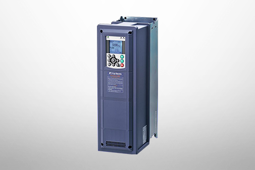
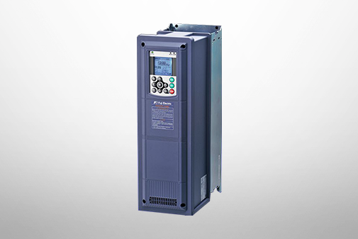
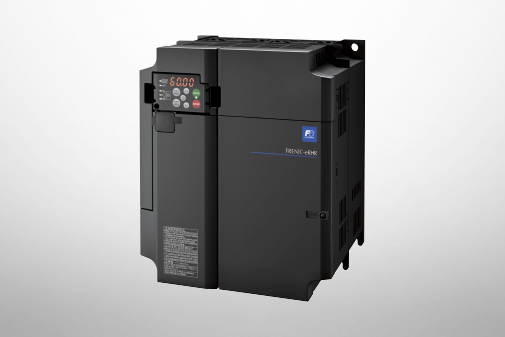
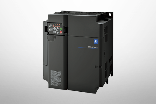
FRENIC-HVAC
Standard Specifications | Basic Type


-
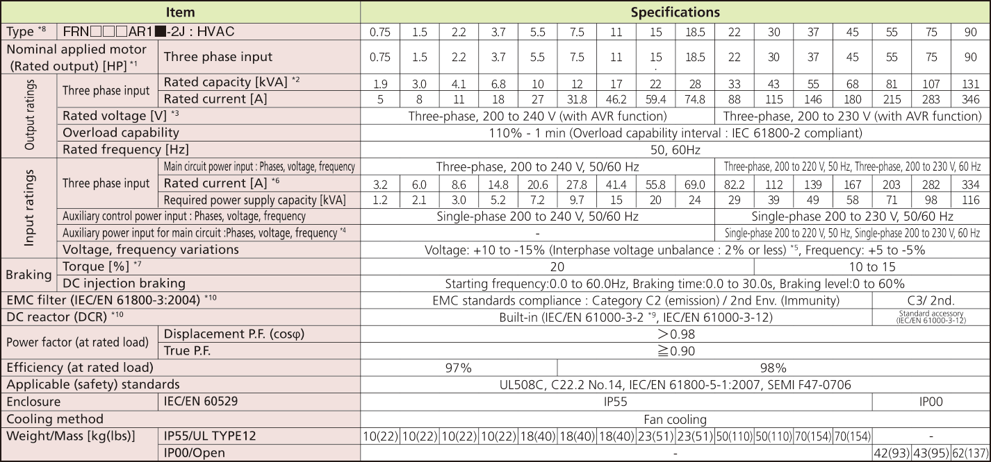
Standard Specifications Basic Type
Three-phase200V (Basic type)
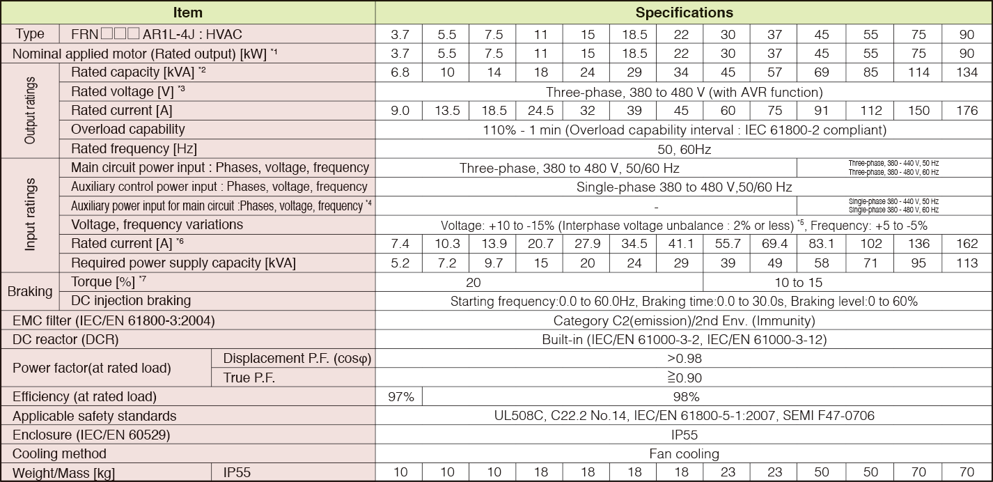
Three-phase400V (Basic type)
-
Note1
-
Fuji 4-pole standard motor.
-
Note2
-
Rated capacity is calculated by assuming the output rated voltage as 440 V.
-
Note3
-
Output voltage cannot exceed the power supply voltage.
-
Note4
-
The auxiliary power input is used as an AC power input when combining the unit to DC power supply such as high power factor PWM converter with power regenerative function. (Generally not to be used.)
-
Note5
-
Voltage unbalance [%] = (Max. voltage [V] - Min. voltage [V])/Three-phase average voltage [V] x 67 (See IEC61800-3.) If this value is 2 to 3%, use an optional AC reactor (ACR).
-
Note6
-
The value is calculated on assumption that the inverter is connected with a power supply 400V, 50Hz and Rsce=120.
-
Note7
-
Average braking torque for the motor running alone. (It varies with the efficiency of the motor.)


-
Standard Specifications Basic Type
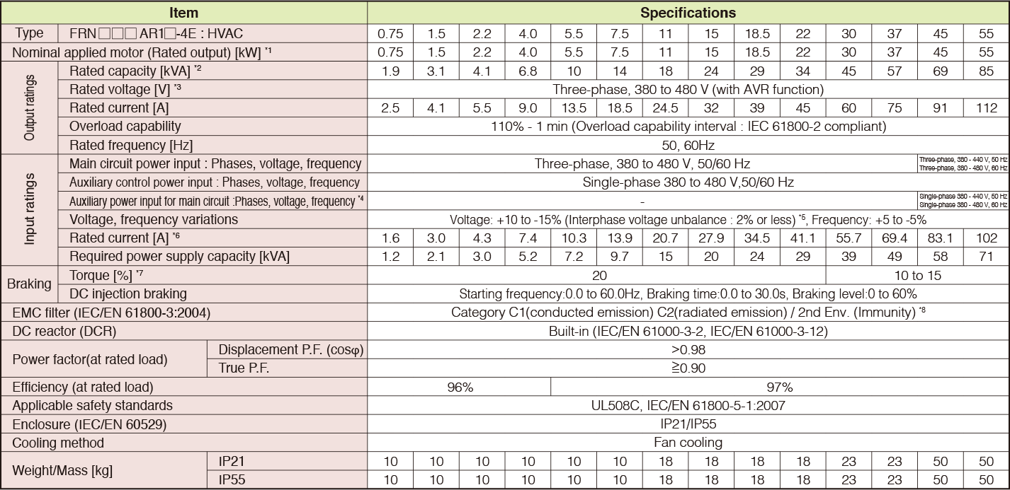
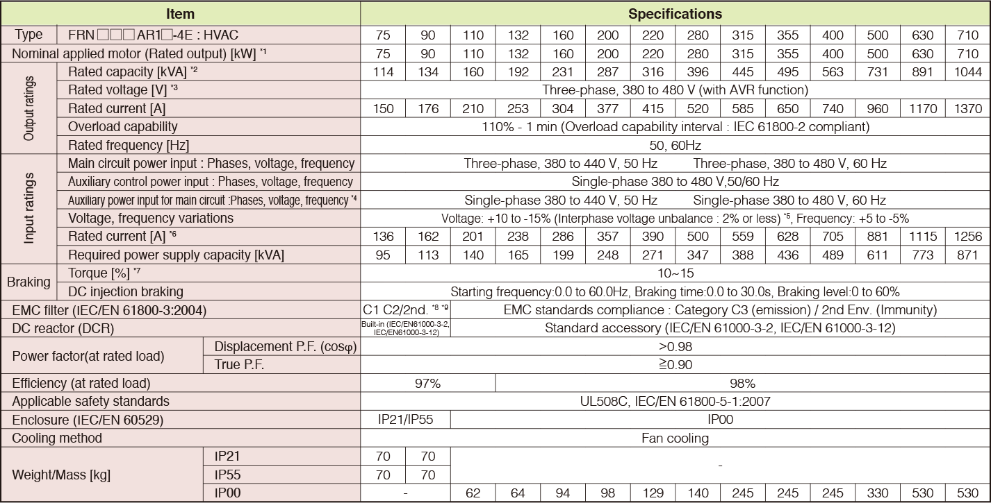
Three-phase400V (Basic type)
0.75 to 55kW
75 to 710kW
-
Note1
-
Fuji 4-pole standard motor.
-
Note2
-
Rated capacity is calculated by assuming the output rated voltage as 440 V.
-
Note3
-
Output voltage cannot exceed the power supply voltage.
-
Note4
-
The auxiliary power input is used as an AC power input when combining the unit to DC power supply such as high power factor PWM converter with power regenerative function. (Generally not to be used.)
-
Note5
-
Voltage unbalance [%] = (Max. voltage [V] - Min. voltage [V])/Three-phase average voltage [V] x 67 (See IEC61800-3.) If this value is 2 to 3%, use an optional AC reactor (ACR).
-
Note6
-
The value is calculated on assumption that the inverter is connected with a power supply 400V, 50Hz and Rsce=120.
-
Note7
-
Average braking torque for the motor running alone. (It varies with the efficiency of the motor.)
-
Note8
-
To provide compatibility for EMC category C1, ensure a motor power cable leng h of 10 m or less, a carrier frequency of 4kHz or less, and ground the E1 and E2 terminals.
-
Note9
-
Category C1(conducted emission) C2(radiated emission) / 2nd Env. (Immunity)


-
Standard Specifications Basic Type
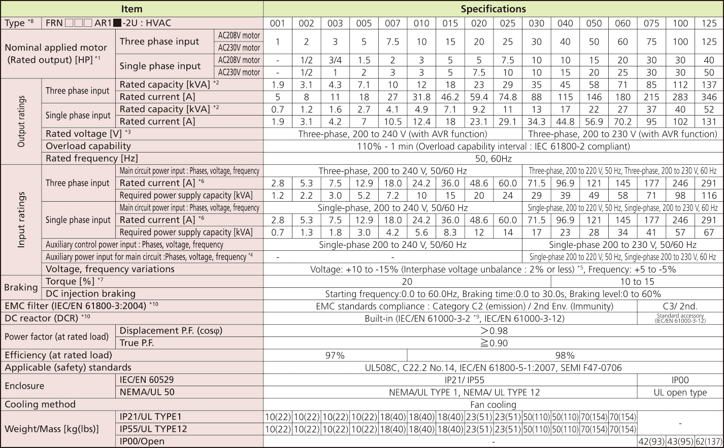
Three-phase230V (Basic type)
1 to 125HP
-
Note1
-
US 4-pole standard induction motor.
-
Note2
-
Rated capacity is calculated by assuming the output rated voltage as 230 V.
-
Note3
-
Output voltage cannot exceed the power supply voltage. At single-phase input use, the output voltage may be lower than three-phase input.
-
Note4
-
The auxiliary power input is used as an AC power input when combining the unit to DC power supply such as high power factor PWM converter with power regenerative function. (Generally not to be used.)
-
Note5
-
Voltage unbalance [%] = (Max. voltage [V] - Min. voltage [V])/Three-phase average voltage [V] x 67 (See IEC61800-3.)If this value is 2 to 3%, use an optional AC reactor (ACR).
-
Note6
-
The value is calculated on assumption that the inverter is connected with a power supply 230V, 50Hz and Rsce=120.
-
Note7
-
Average braking torque for the motor running alone. (It varies with the efficiency of the motor.)
-
Note8
-
The box (□) replaces an numeric letter depending on the drive capacity.
The box (■) replaces an alphabetic letter depending on the enclosure. M (IP21/UL TYPE1), L (IP55/UL TYPE12) or S (IP00/Open)
-
Note9
-
It is applicable when the power supply is supplied from 3-phase 200V series transformer which is through 3-phase 400V series transformer.
-
Note10
-
EMC filters and DCR does not conform to each corresponding standards when single phase input use.
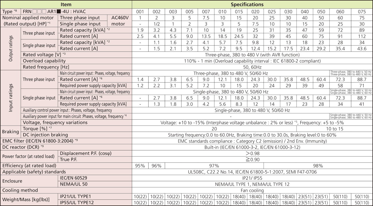
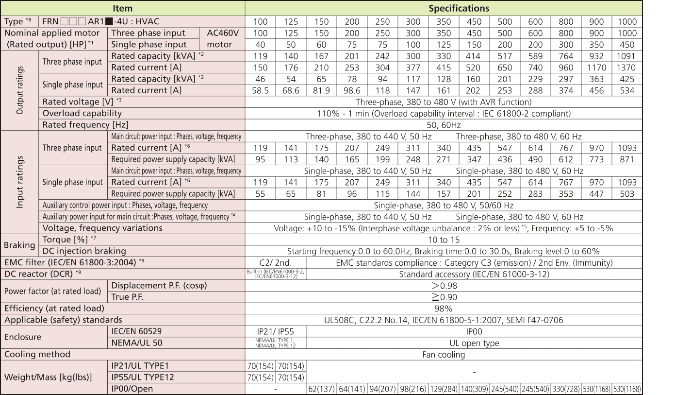
Three-phase460V (Basic type)
1 to 75HP
100 to 1000 HP
-
Note1
-
US 4-pole standard induction motor.
-
Note2
-
Rated capacity is calculated by assuming the output rated voltage as 460 V.
-
Note3
-
Output voltage cannot exceed the power supply voltage. At single-phase input use, the output voltage may be lower than three-phase input.
-
Note4
-
The auxiliary power input is used as an AC power input when combining the unit to DC power supply such as high power factor PWM converter with power regenerative function. (Generally not to be used.)
-
Note5
-
Voltage unbalance [%] = (Max. voltage [V] - Min. voltage [V])/Three-phase average voltage [V] x 67 (See IEC61800-3.) If this value is 2 to 3%, use an optional AC reactor (ACR).
-
Note6
-
The value is calculated on assumption that the inverter is connected with a power supply 460V, 50Hz and Rsce=120.
-
Note7
-
Average braking torque for the motor running alone. (It varies with the efficiency of the motor.)
-
Note8
-
The box (□) replaces an numeric letter depending on the drive capacity. The box (■) replaces an alphabetic letter depending on the enclosure. M (IP21/UL TYPE1), L (IP55/UL TYPE12) or S (IP00/Open)
-
Note9
-
EMC filters and DCR does not conform to each corresponding standards when single phase input use.
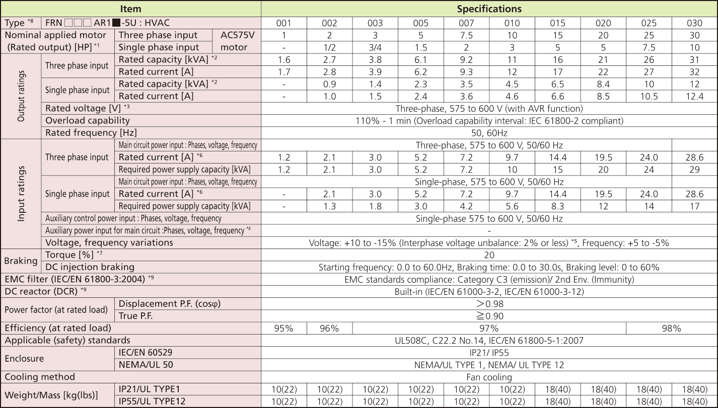
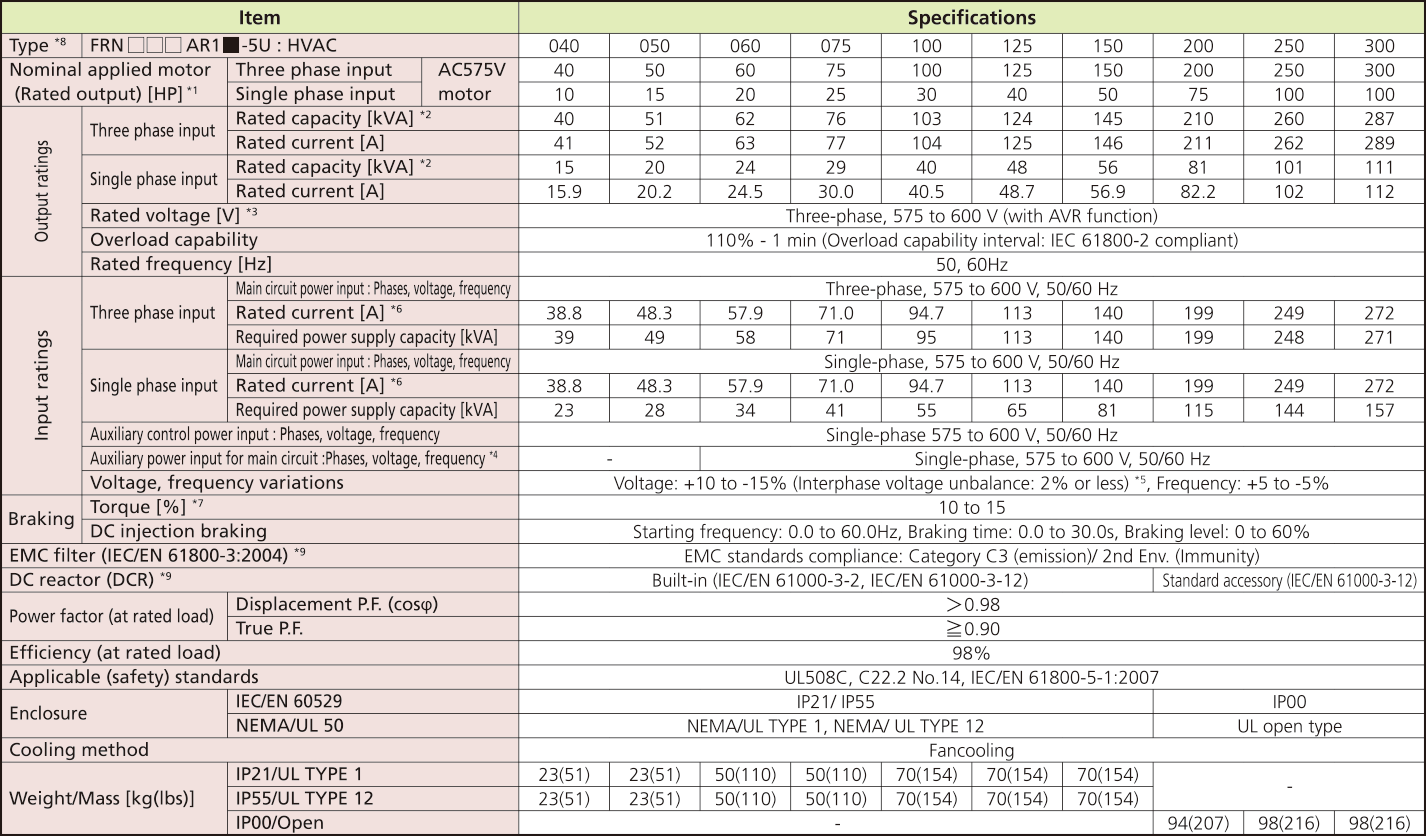
Three-phase575V (Basic type)
1 to 30HP
40 to 300HP
-
Note1
-
US 4-pole standard induction motor.
-
Note2
-
Rated capacity is calculated by assuming the output rated voltage as 575 V.
-
Note3
-
Output voltage cannot exceed the power supply voltage. At single-phase input use, the output voltage may be lower than three-phase input.
-
Note4
-
The auxiliary power input is used as an AC power input when combining the unit to DC power supply such as high power factor PWM converter with power regenerative function. (Generally not to be used.)
-
Note5
-
Voltage unbalance [%] = (Max. voltage [V] - Min. voltage [V])/Three-phase average voltage [V] x 67 (See IEC61800-3.) If this value is 2 to 3%, use an optional AC reactor (ACR).
-
Note6
-
The value is calculated on assumption that the inverter is connected with a power supply 575V, 50Hz and Rsce=120.
-
Note7
-
Average braking torque for the motor running alone. (It varies with the efficiency of the motor.)
-
Note8
-
The underline (□) replaces an numeric letter depending on the drive capacity. The box (■) replaces an alphabetic letter depending on the enclosure. M (IP21), L (IP55) or S (IP00)
-
Note9
-
EMC filters and DCR does not conform to each corresponding standards when single phase input use.
This type is not available in this region.
If you need more information for this products, please contact us through the inquiry form.


-
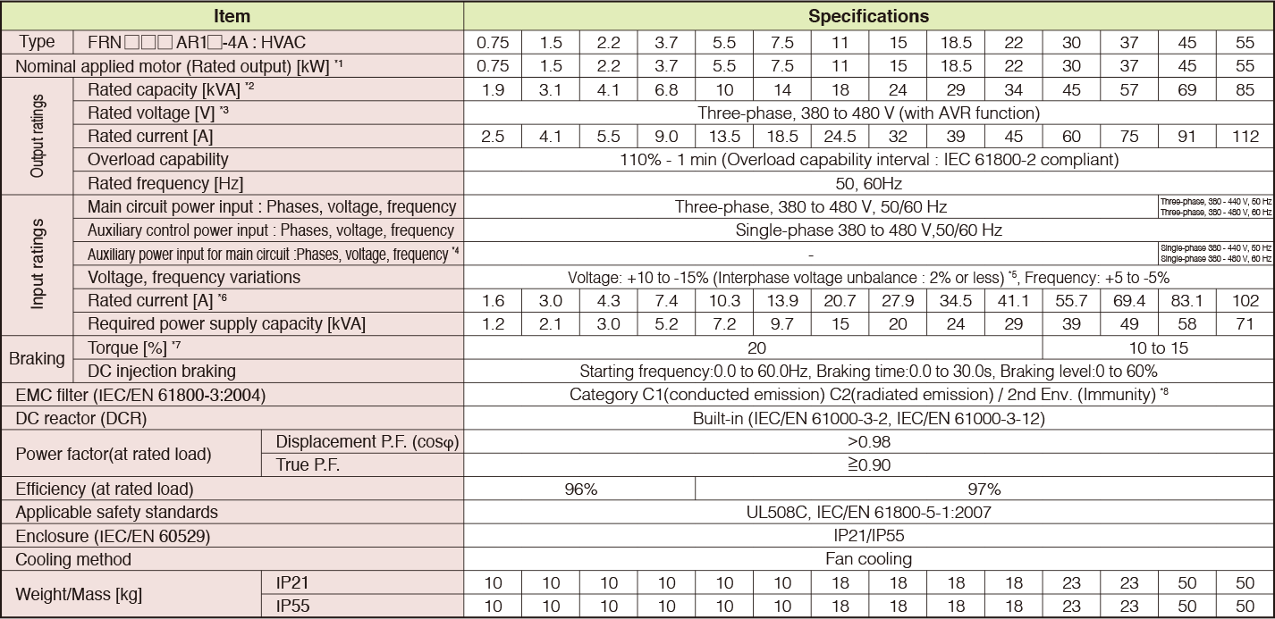
Standard Specifications Basic Type
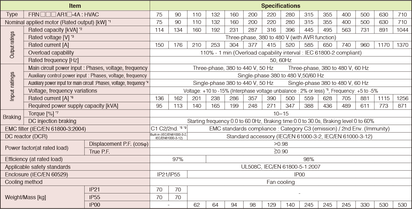
Three-phase400V (Basic type)
0.75 to 55kW
75 to 710kW
-
Note1
-
Fuji 4-pole standard motor.
-
Note2
-
Rated capacity is calculated by assuming the output rated voltage as 440 V.
-
Note3
-
Output voltage cannot exceed the power supply voltage.
-
Note4
-
The auxiliary power input is used as an AC power input when combining the unit to DC power supply such as high power factor PWM converter with power regenerative function. (Generally not to be used.)
-
Note5
-
Voltage unbalance [%] = (Max. voltage [V] - Min. voltage [V])/Three-phase average voltage [V] x 67 (See IEC61800-3.) If this value is 2 to 3%, use an optional AC reactor (ACR).
-
Note6
-
The value is calculated on assumption that the inverter is connected with a power supply 400V, 50Hz and Rsce=120.
-
Note7
-
Average braking torque for the motor running alone. (It varies with the efficiency of the motor.)
-
Note8
-
To provide compatibility for EMC category C1, ensure a motor power cable leng h of 10 m or less, a carrier frequency of 4kHz or less, and ground the E1 and E2 terminals.
-
Note9
-
Category C1(conducted emission) C2(radiated emission) / 2nd Env. (Immunity)
This type is not available in this region.
If you need more information for this products, please contact us through the inquiry form.
This type is not available in this region.
If you need more information for this products, please contact us through the inquiry form.
AC Drives (Low Voltage) Support
Download documents
Column
Understanding application, benefits, basic structure, case study, types, and Fuji Electric's inverters with this video.
December 27,2021

Understanding the basics: Differences between inverters and converters
January 20,2021

How and what does an inverter take control of? A brief explanation to grasp the basic structure.
January 20,2021

The fundamentals of inverters and their uses.
January 20,2021


