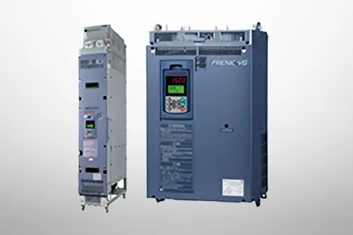
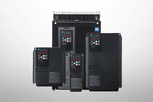
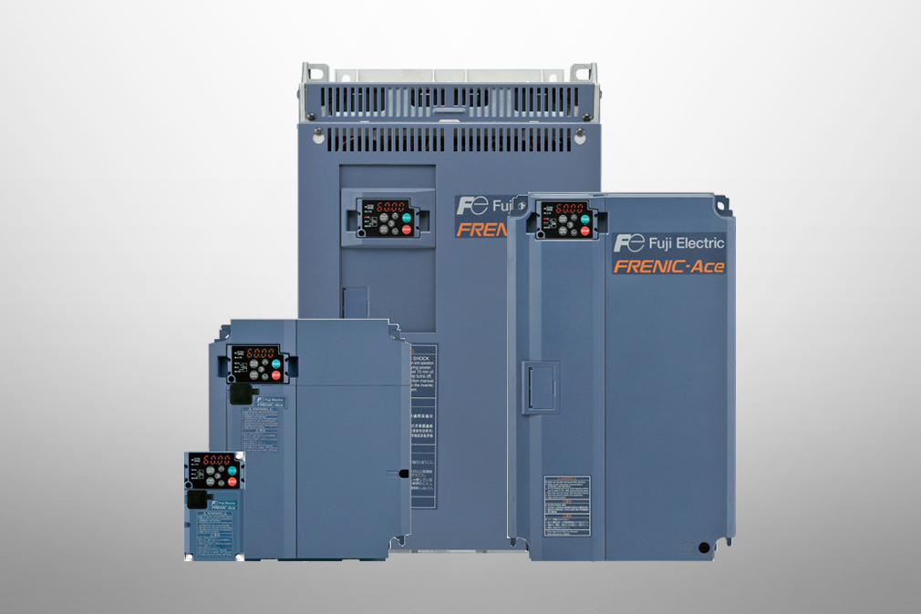
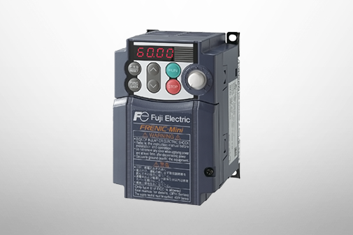
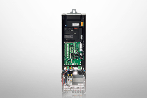
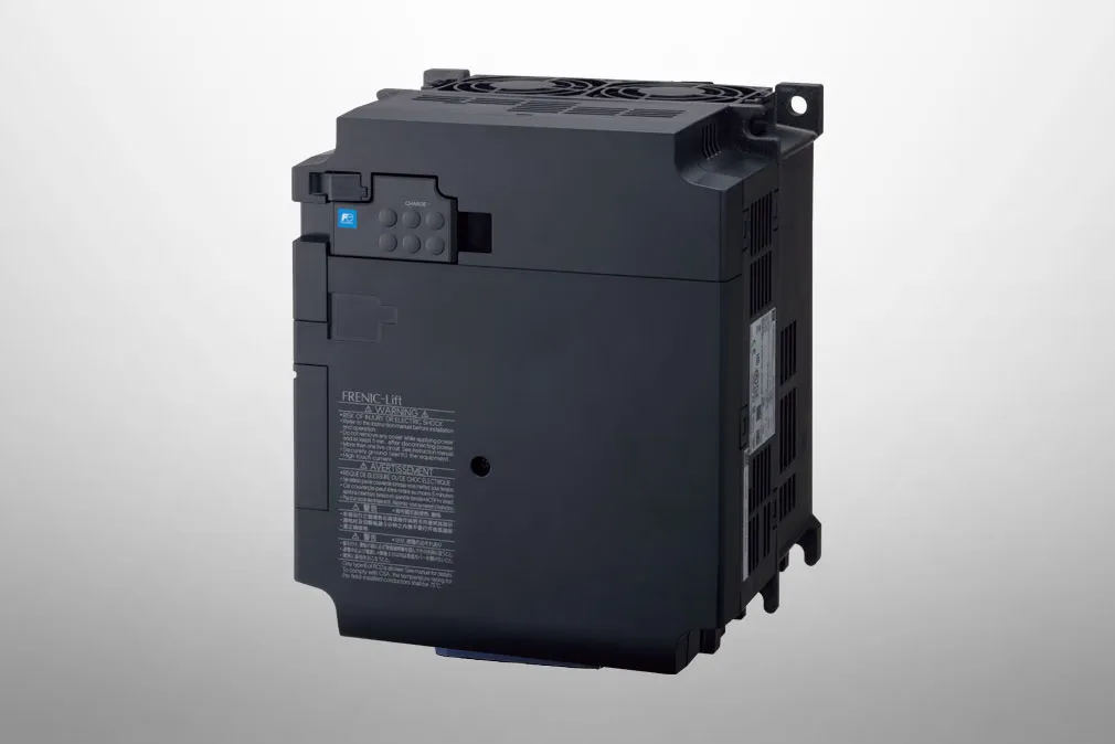
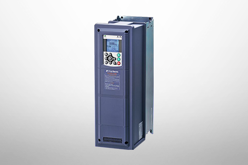
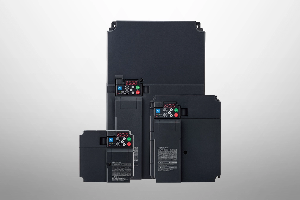
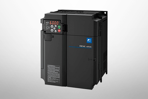
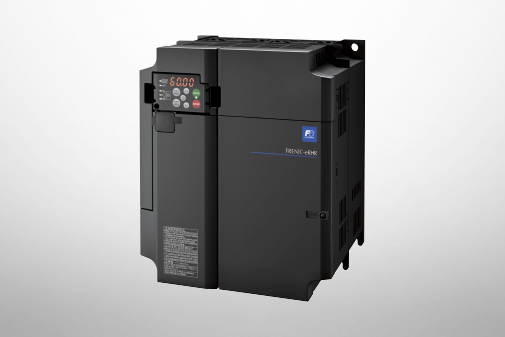
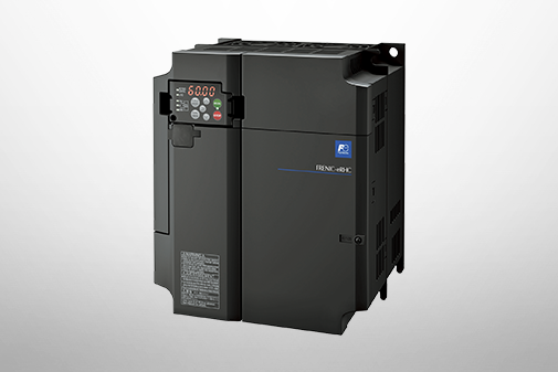
FRENIC-MEGA (G1)
Specifications | Basic type(200V)

Basic type
Three-phase 200V series
HD (High Duty) spec for heavy load
LD (Low Duty) spec for light load

*1

Fuji's 4-pole standard motor

*2

Rated capacity is calculated by assuming the output rated voltage as 220V for three-phase 200V series and 440V for three-phase 400V series.

*3

Output voltage cannot exceed the power supply voltage.

*4

When using the inverter in the ambient temperature of 40℃ or over and with carrier frequency at 3kHz or higher, adjust the current under continuous running to be the value in ( ) or lower by controlling the load.

*5

The auxiliary power input is used as an AC fan power input when combining the unit such as high power factor PWM converter with power regenerative function. (Generally not used.)

*6

Interphase voltage unbalance ratio[%] = (max. voltage [V] - min. voltage [V])/3-phase average voltage [V]×67(See IEC61800-3.) Use the DC reactor (ACR: optional) when used with 2 to 3 % of unbalance ratio.

*7

The value is calculated on assumption that the inverter is connected with a power supply capacity of 500kVA (or 10 times the inverter capacity if the inverter capacity exceeds 50kVA) and %X is 5%.

*8

Obtained when a DC reactor (DCR) is used.

*9

Average braking torque obtained by use of a motor. (Varies with the efficiency of the motor.)

Three-phase 230V series
LD (Low Duty)-mode inverters for light load
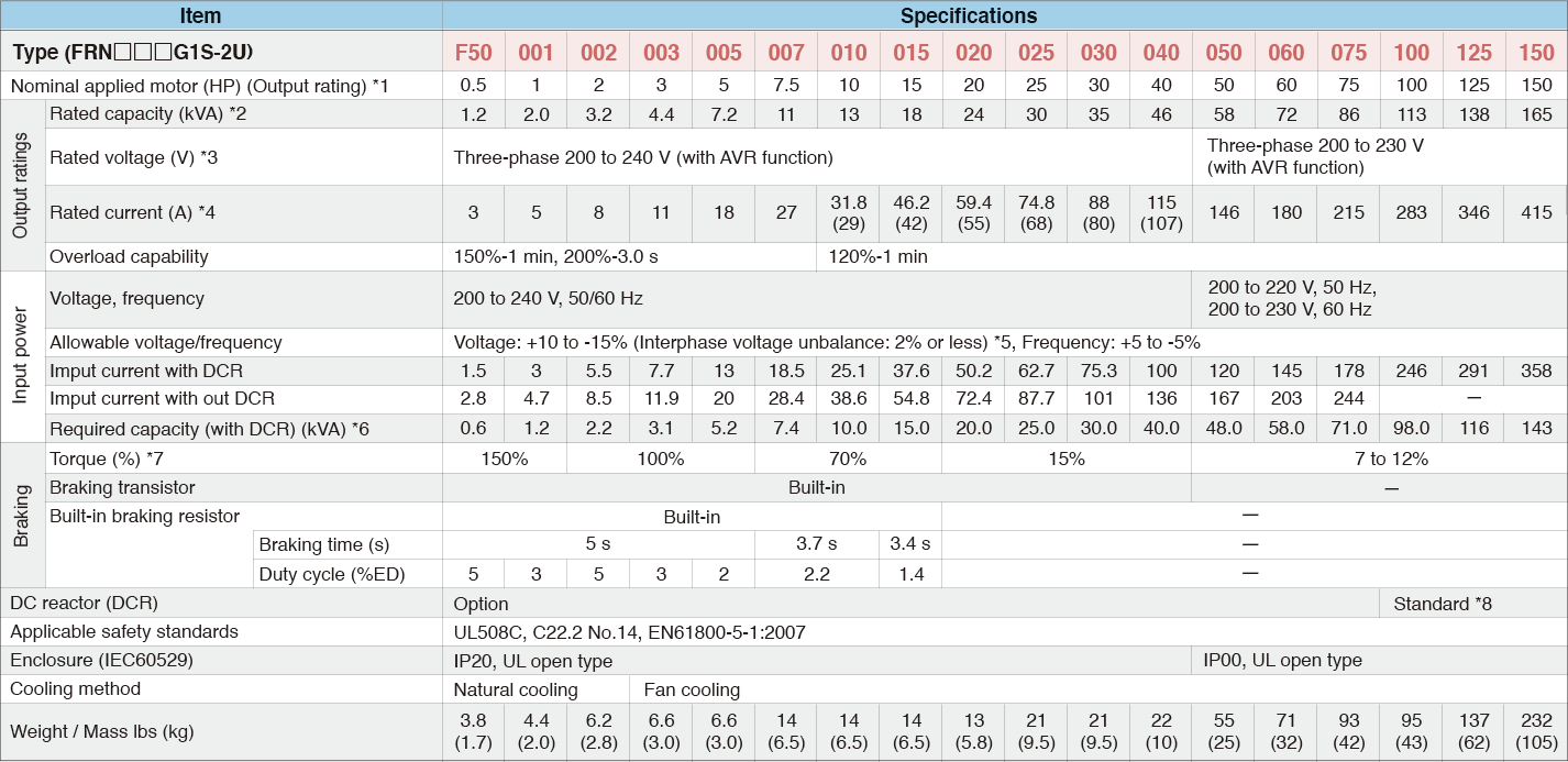
*1

US 4P-standard induction motor

*2

Rated capacity is calculated assuming the rated output voltage as 230 V for 230 V series and 460 V for 460 V series.

*3

Output voltage cannot exceed the power supply voltage.

*4

To use the inverter with the carrier frequency of 3 kHz or more at the surrounding temperature of 40°C (104°F) or higher, manage the load so that the current comes to be within the rated ones enclosed in parentheses ( ) in continuous running.

*5

Voltage unbalance (%) = (Max. voltage (V) - Min. voltage (V) / Three-phase average voltage (V)) × 67 (IEC 61800- 3)U
If this value is 2 to 3%, use an optional AC reactor (ACR).

*6

Required when a DC reactor (DCR) is used.

*7

Average braking torque for the motor running alone, without external braking resistor. (It varies with the efficiency of the motor.)

*8

The FRN100G1S-2U or higher type comes with a DC reactor (DCR).

HD (High Duty)-mode inverters for heavy load
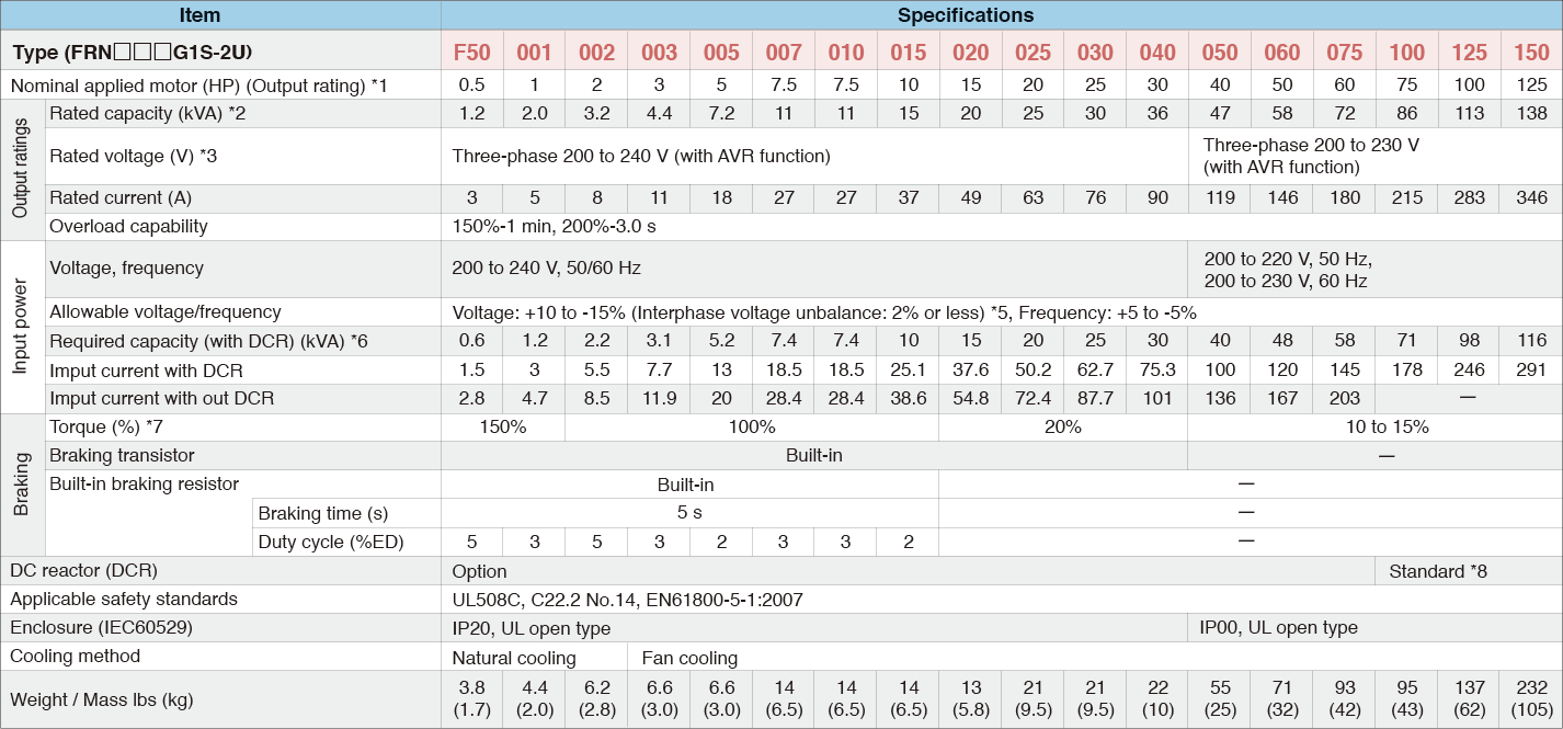
*1

US 4P-standard induction motor

*2

Rated capacity is calculated assuming the rated output voltage as 230 V for 230 V series and 460 V for 460 V series.

*3

Output voltage cannot exceed the power supply voltage.

*5

Voltage unbalance (%) = (Max. voltage (V) - Min. voltage (V) / Three-phase average voltage (V)) × 67 (IEC 61800- 3)U
If this value is 2 to 3%, use an optional AC reactor (ACR).

*6

Required when a DC reactor (DCR) is used.

*7

Average braking torque for the motor running alone, without external braking resistor. (It varies with the efficiency of the motor.)

*8

The FRN100G1S-2U or higher type comes with a DC reactor (DCR).

Three-phase 200V series
HD (High Duty) spec for heavy load
LD (Low Duty) spec for light load

*1

Fuji's 4-pole standard motor

*2

Rated capacity is calculated by assuming the output rated voltage as 220V for three-phase 200V series and 440V for three-phase 400V series.

*3

Output voltage cannot exceed the power supply voltage.

*4

When using the inverter in the ambient temperature of 40℃ or over and with carrier frequency at 3kHz or higher, adjust the current under continuous running to be the value in ( ) or lower by controlling the load.

*5

The auxiliary power input is used as an AC fan power input when combining the unit such as high power factor PWM converter with power regenerative function. (Generally not used.)

*6

Interphase voltage unbalance ratio[%] = (max. voltage [V] - min. voltage [V])/3-phase average voltage [V]×67(See IEC61800-3.) Use the DC reactor (ACR: optional) when used with 2 to 3 % of unbalance ratio.

*7

The value is calculated on assumption that the inverter is connected with a power supply capacity of 500kVA (or 10 times the inverter capacity if the inverter capacity exceeds 50kVA) and %X is 5%.

*8

Obtained when a DC reactor (DCR) is used.

*9

Average braking torque obtained by use of a motor. (Varies with the efficiency of the motor.)

*10

A DC reactor (DCR) is an option. However, Inverters with a capacity of 75kW(HD spec) or above, 55kW(LD spec) or above, require a DCR to be connected. Be sure to connect it to those inverters.