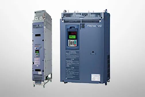




FRENIC-VG
Specifications | Stack Type MD specifications for middle overload
-
Stack Type MD specifications for middle overload
Three-phase 400V

Three-phase 690V

-
Note1
-
The specifications above apply when function code F80 = 0, 2, 3 (MD specification). (Default = 0) If F80 = 0, 2, "HD" appears on keypad.
When the rated output voltage is 440 V (400V series) or 690 V (690V series).
-
Note2
-
When the converted inverter output frequency is less than 1Hz, the inverter may trip earlier in some ambient temperature conditions if the motor is overloaded.
-
Note3
-
400V series: When the power supply is 380 to 398 V at 50Hz, or 380 to 430 V at 60Hz, a connector inside the inverter must be reconnected accordingly.
690V series: When the power supply is 575 to 600 V at 50Hz/60Hz, a connector inside the inverter must be reconnected accordingly.
-
Note4
-
If running a synchronous motor at low carrier frequency, there is a risk of demagnetization due to permanent magnet overheating as a result of output current harmonics.
The carrier frequency is low (2kHz), and therefore the motor allowable carrier frequency must always be checked.
-
Note5
-
One set of the inverter consists of three stacks.
-
Note6
-
The nominal applied motor capacity is for a 690 V motor.
For motors of differing voltage specifications and detailed selections, select a capacity that will ensure that the inverter rated current is equal to or greater than the motor rated current.
-
Stack Type MD specifications for middle overload
Three-phase 400V

Three-phase 690V

-
Note1
-
The specifications above apply when function code F80 = 0, 2, 3 (MD specification). (Default = 0) If F80 = 0, 2, "HD" appears on keypad.
When the rated output voltage is 440 V (400V series) or 690 V (690V series).
-
Note2
-
When the converted inverter output frequency is less than 1Hz, the inverter may trip earlier in some ambient temperature conditions if the motor is overloaded.
-
Note3
-
400V series: When the power supply is 380 to 398 V at 50Hz, or 380 to 430 V at 60Hz, a connector inside the inverter must be reconnected accordingly.
690V series: When the power supply is 575 to 600 V at 50Hz/60Hz, a connector inside the inverter must be reconnected accordingly.
-
Note4
-
If running a synchronous motor at low carrier frequency, there is a risk of demagnetization due to permanent magnet overheating as a result of output current harmonics.
The carrier frequency is low (2kHz), and therefore the motor allowable carrier frequency must always be checked.
-
Note5
-
One set of the inverter consists of three stacks.
-
Note6
-
The nominal applied motor capacity is for a 690 V motor.
For motors of differing voltage specifications and detailed selections, select a capacity that will ensure that the inverter rated current is equal to or greater than the motor rated current.
-
Stack Type MD specifications for middle overload
Three-phase 400V

Three-phase 690V

-
Note 1
-
The specifications above apply when function code F80 = 0, 2, 3 (MD specification). (Default = 0) If F80 = 0, 2, "HD" appears on keypad.
When the rated output voltage is 440 V (400V series) or 690 V (690V series).
-
Note2
-
When the converted inverter output frequency is less than 1Hz, the inverter may trip earlier in some ambient temperature conditions if the motor is overloaded.
-
Note3
-
400V series: When the power supply is 380 to 398 V at 50Hz, or 380 to 430 V at 60Hz, a connector inside the inverter must be reconnected accordingly.
690V series: When the power supply is 575 to 600 V at 50Hz/60Hz, a connector inside the inverter must be reconnected accordingly.
-
Note4
-
If running a synchronous motor at low carrier frequency, there is a risk of demagnetization due to permanent magnet overheating as a result of output current harmonics.
The carrier frequency is low (2kHz), and therefore the motor allowable carrier frequency must always be checked.
-
Note5
-
One set of the inverter consists of three stacks.
-
Note6
-
The nominal applied motor capacity is for a 690 V motor.
For motors of differing voltage specifications and detailed selections, select a capacity that will ensure that the inverter rated current is equal to or greater than the motor rated current.
-
Stack Type MD specifications for middle overload
Three-phase 400V

Three-phase 690V

-
Note 1
-
The specifications above apply when function code F80 = 0, 2, 3 (MD specification). (Default = 0) If F80 = 0, 2, "HD" appears on keypad.
When the rated output voltage is 440 V (400V series) or 690 V (690V series).
-
Note2
-
When the converted inverter output frequency is less than 1Hz, the inverter may trip earlier in some ambient temperature conditions if the motor is overloaded.
-
Note3
-
400V series: When the power supply is 380 to 398 V at 50Hz, or 380 to 430 V at 60Hz, a connector inside the inverter must be reconnected accordingly.
690V series: When the power supply is 575 to 600 V at 50Hz/60Hz, a connector inside the inverter must be reconnected accordingly.
-
Note4
-
If running a synchronous motor at low carrier frequency, there is a risk of demagnetization due to permanent magnet overheating as a result of output current harmonics.
The carrier frequency is low (2kHz), and therefore the motor allowable carrier frequency must always be checked.
-
Note5
-
One set of the inverter consists of three stacks.
-
Note6
-
The nominal applied motor capacity is for a 690 V motor.
For motors of differing voltage specifications and detailed selections, select a capacity that will ensure that the inverter rated current is equal to or greater than the motor rated current.
-
Stack Type MD specifications for middle overload
Three-phase 400V

Three-phase 690V

-
Note1
-
The specifications above apply when function code F80 = 0, 2, 3 (MD specification). (Default = 0) If F80 = 0, 2, "HD" appears on keypad.
When the rated output voltage is 440 V (400V series) or 690 V (690V series).
-
Note2
-
When the converted inverter output frequency is less than 1Hz, the inverter may trip earlier in some ambient temperature conditions if the motor is overloaded.
-
Note3
-
400V series: When the power supply is 380 to 398 V at 50Hz, or 380 to 430 V at 60Hz, a connector inside the inverter must be reconnected accordingly.
690V series: When the power supply is 575 to 600 V at 50Hz/60Hz, a connector inside the inverter must be reconnected accordingly.
-
Note4
-
If running a synchronous motor at low carrier frequency, there is a risk of demagnetization due to permanent magnet overheating as a result of output current harmonics.
The carrier frequency is low (2kHz), and therefore the motor allowable carrier frequency must always be checked.
-
Note5
-
One set of the inverter consists of three stacks.
-
Note6
-
The nominal applied motor capacity is for a 690 V motor.
For motors of differing voltage specifications and detailed selections, select a capacity that will ensure that the inverter rated current is equal to or greater than the motor rated current.
-
Stack Type MD specifications for middle overload
Three-phase 400V

Three-phase 690V

-
Note1
-
The specifications above apply when function code F80 = 0, 2, 3 (MD specification). (Default = 0) If F80 = 0, 2, "HD" appears on keypad.
When the rated output voltage is 440 V (400V series) or 690 V (690V series).
-
Note2
-
When the converted inverter output frequency is less than 1Hz, the inverter may trip earlier in some ambient temperature conditions if the motor is overloaded.
-
Note3
-
400V series: When the power supply is 380 to 398 V at 50Hz, or 380 to 430 V at 60Hz, a connector inside the inverter must be reconnected accordingly.
690V series: When the power supply is 575 to 600 V at 50Hz/60Hz, a connector inside the inverter must be reconnected accordingly.
-
Note4
-
If running a synchronous motor at low carrier frequency, there is a risk of demagnetization due to permanent magnet overheating as a result of output current harmonics.
The carrier frequency is low (2kHz), and therefore the motor allowable carrier frequency must always be checked.
-
Note5
-
One set of the inverter consists of three stacks.
-
Note6
-
The nominal applied motor capacity is for a 690 V motor.
For motors of differing voltage specifications and detailed selections, select a capacity that will ensure that the inverter rated current is equal to or greater than the motor rated current.
-
Stack Type MD specifications for middle overload
Three-phase 400V

Three-phase 690V

-
Note1
-
The specifications above apply when function code F80 = 0, 2, 3 (MD specification). (Default = 0) If F80 = 0, 2, "HD" appears on keypad.
When the rated output voltage is 440 V (400V series) or 690 V (690V series).
-
Note2
-
When the converted inverter output frequency is less than 1Hz, the inverter may trip earlier in some ambient temperature conditions if the motor is overloaded.
-
Note3
-
400V series: When the power supply is 380 to 398 V at 50Hz, or 380 to 430 V at 60Hz, a connector inside the inverter must be reconnected accordingly.
690V series: When the power supply is 575 to 600 V at 50Hz/60Hz, a connector inside the inverter must be reconnected accordingly.
-
Note4
-
If running a synchronous motor at low carrier frequency, there is a risk of demagnetization due to permanent magnet overheating as a result of output current harmonics.
The carrier frequency is low (2kHz), and therefore the motor allowable carrier frequency must always be checked.
-
Note5
-
One set of the inverter consists of three stacks.
-
Note6
-
The nominal applied motor capacity is for a 690 V motor.
For motors of differing voltage specifications and detailed selections, select a capacity that will ensure that the inverter rated current is equal to or greater than the motor rated current.