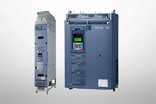
FRENIC-VG
Specifications | Unit Type LD Specifications for Light Overload


-
Unit Type LD Specifications for Light Overload
Three-phase 200V

Three-phase 400V

-
Note1
-
The above specifications are for Function Code F80=1 (LD specification).
If using with an LD specification of 55kW or higher, specify LD specification when placing your order.
With the type FRN□ VG1S-□ J, a DC reactor with nominal applied motor capacity is provided as standard.
The rated output voltage is 220V for 200V series and 440V for 400V series.
-
Note2
-
When using a DC reactor, refer to the following.
・Type FRN□ VG1S-□ J: 45kW or below: provided as option, 55kW or above: provided as standard.
(Specify LD specification when placing your order.)
When the converted inverter output frequency is less than 10Hz, the inverter may trip earlier in some ambient temperature conditions if the motor is overloaded.
-
Note3
-
200V series: Make an individual order for 220 to 230V/50Hz.
400V series: The inverters with the power supply of 380 to 398V/50Hz and 380 to 430V/60Hz must be switched using a connector inside the inverter.
The output of the inverter with 380V may drop depending on situations. For details, refer to Chapter 10 in the FRENIC-VG User Manual "Unit Type, Function Code Edition" 24A- -0019.
-
Note4
-
The auxiliary power input is used as an AC fan power input when combining the unit such as high power factor PWM converter with power regenerative function.(Generally not used.)
-
Note5
-
Voltage unbalance [%] = (Max. voltage [V] - Min. voltage [V]) / (Three-phase average voltage [V]) × 67
Use an AC reactor if the voltage unbalance exceeds 2%.
-
Note6
-
The value is calculated on assumption that the inverter is connected with a power supply capacity of 500kVA (or 10 times the inverter capacity if the inverter capacity exceeds 50kVA) and %X is 5%.
-
Note7
-
The values shown apply when a DC reactor is used.
If using a generator for the power source, it may burn out with high-frequency current from the inverter. Use a generator with 3 to 4 times the specified power supply capacity.
(When DC reactor not connected: approx. 4 times specified power supply capacity, when DC reactor connected: approx. 3 times specified power supply capacity)
-
Note8
-
The inverter may automatically reduce carrier frequency in accordance with ambient temperature or output current in order to protect itself.
If the carrier frequency auto reduction selection (H104: digit 100) is cancelled, the unit continuous rated current will drop depending on the carrier frequency setting, and therefore caution is advised.
(For details, refer to Chapter 2 in the FRENIC-VG User Manual "Unit Type, Function Code Edition" 24A7-□-0019.)
-
Unit Type LD Specifications for Light Overload
Three-phase 200V

Three-phase 400V

-
Note1
-
The above specifications are for Function Code F80=1 (LD specification).
If using with an LD specification of 55kW or higher, specify LD specification when placing your order.
With the type FRN□ VG1S-□ J, a DC reactor with nominal applied motor capacity is provided as standard.
The rated output voltage is 220V for 200V series and 440V for 400V series.
-
Note2
-
When using a DC reactor, refer to the following.
・Type FRN□VG1S-□E : All capacities are provided as option.
When the converted inverter output frequency is less than 10Hz, the inverter may trip earlier in some ambient temperature conditions if the motor is overloaded.
-
Note3
-
200V series: Make an individual order for 220 to 230V/50Hz.
400V series: The inverters with the power supply of 380 to 398V/50Hz and 380 to 430V/60Hz must be switched using a connector inside the inverter.
The output of the inverter with 380V may drop depending on situations. For details, refer to Chapter 10 in the FRENIC-VG User Manual "Unit Type, Function Code Edition" 24A- -0019.
-
Note4
-
The auxiliary power input is used as an AC fan power input when combining the unit such as high power factor PWM converter with power regenerative function.(Generally not used.)
-
Note5
-
Voltage unbalance [%] = (Max. voltage [V] - Min. voltage [V]) / (Three-phase average voltage [V]) × 67
Use an AC reactor if the voltage unbalance exceeds 2%.
-
Note6
-
The value is calculated on assumption that the inverter is connected with a power supply capacity of 500kVA (or 10 times the inverter capacity if the inverter capacity exceeds 50kVA) and %X is 5%.
-
Note7
-
The values shown apply when a DC reactor is used.
If using a generator for the power source, it may burn out with high-frequency current from the inverter. Use a generator with 3 to 4 times the specified power supply capacity.
(When DC reactor not connected: approx. 4 times specified power supply capacity, when DC reactor connected: approx. 3 times specified power supply capacity)
-
Note8
-
The inverter may automatically reduce carrier frequency in accordance with ambient temperature or output current in order to protect itself.
If the carrier frequency auto reduction selection (H104: digit 100) is cancelled, the unit continuous rated current will drop depending on the carrier frequency setting, and therefore caution is advised.
(For details, refer to Chapter 2 in the FRENIC-VG User Manual "Unit Type, Function Code Edition" 24A7-□-0019.)
-
Unit Type LD Specifications for Light Overload
Three-phase 200V

Three-phase 400V

-
Note1
-
The above specifications are for Function Code F80=1 (LD specification).
If using with an LD specification of 55kW or higher, specify LD specification when placing your order.
With the type FRN□ VG1S-□ J, a DC reactor with nominal applied motor capacity is provided as standard.
The rated output voltage is 220V for 200V series and 440V for 400V series.
-
Note2
-
When using a DC reactor, refer to the following.
・Type FRN□VG1S-□C : All capacities are provided as option.
When the converted inverter output frequency is less than 10Hz, the inverter may trip earlier in some ambient temperature conditions if the motor is overloaded.
-
Note3
-
200V series: Make an individual order for 220 to 230V/50Hz.
400V series: The inverters with the power supply of 380 to 398V/50Hz and 380 to 430V/60Hz must be switched using a connector inside the inverter.
The output of the inverter with 380V may drop depending on situations. For details, refer to Chapter 10 in the FRENIC-VG User Manual "Unit Type, Function Code Edition" 24A- -0019.
-
Note4
-
The auxiliary power input is used as an AC fan power input when combining the unit such as high power factor PWM converter with power regenerative function.(Generally not used.)
-
Note5
-
Voltage unbalance [%] = (Max. voltage [V] - Min. voltage [V]) / (Three-phase average voltage [V]) × 67
Use an AC reactor if the voltage unbalance exceeds 2%.
-
Note6
-
The value is calculated on assumption that the inverter is connected with a power supply capacity of 500kVA (or 10 times the inverter capacity if the inverter capacity exceeds 50kVA) and %X is 5%.
-
Note7
-
The values shown apply when a DC reactor is used.
If using a generator for the power source, it may burn out with high-frequency current from the inverter. Use a generator with 3 to 4 times the specified power supply capacity.
(When DC reactor not connected: approx. 4 times specified power supply capacity, when DC reactor connected: approx. 3 times specified power supply capacity)
-
Note8
-
The inverter may automatically reduce carrier frequency in accordance with ambient temperature or output current in order to protect itself.
If the carrier frequency auto reduction selection (H104: digit 100) is cancelled, the unit continuous rated current will drop depending on the carrier frequency setting, and therefore caution is advised.
(For details, refer to Chapter 2 in the FRENIC-VG User Manual "Unit Type, Function Code Edition" 24A7-□-0019.)
-
Unit Type LD Specifications for Light Overload
Three-phase 200V

Three-phase 400V

-
Note1
-
The above specifications are for Function Code F80=1 (LD specification).
If using with an LD specification of 55kW or higher, specify LD specification when placing your order.
With the type FRN□ VG1S-□ J, a DC reactor with nominal applied motor capacity is provided as standard.
The rated output voltage is 220V for 200V series and 440V for 400V series.
-
Note2
-
When using a DC reactor, refer to the following.
・Type FRN□VG1S-□E : All capacities are provided as option.
When the converted inverter output frequency is less than 10Hz, the inverter may trip earlier in some ambient temperature conditions if the motor is overloaded.
-
Note3
-
200V series: Make an individual order for 220 to 230V/50Hz.
400V series: The inverters with the power supply of 380 to 398V/50Hz and 380 to 430V/60Hz must be switched using a connector inside the inverter.
The output of the inverter with 380V may drop depending on situations. For details, refer to Chapter 10 in the FRENIC-VG User Manual "Unit Type, Function Code Edition" 24A- -0019.
-
Note4
-
The auxiliary power input is used as an AC fan power input when combining the unit such as high power factor PWM converter with power regenerative function.(Generally not used.)
-
Note5
-
Voltage unbalance [%] = (Max. voltage [V] - Min. voltage [V]) / (Three-phase average voltage [V]) × 67
Use an AC reactor if the voltage unbalance exceeds 2%.
-
Note6
-
The value is calculated on assumption that the inverter is connected with a power supply capacity of 500kVA (or 10 times the inverter capacity if the inverter capacity exceeds 50kVA) and %X is 5%.
-
Note7
-
The values shown apply when a DC reactor is used.
If using a generator for the power source, it may burn out with high-frequency current from the inverter. Use a generator with 3 to 4 times the specified power supply capacity.
(When DC reactor not connected: approx. 4 times specified power supply capacity, when DC reactor connected: approx. 3 times specified power supply capacity)
-
Note8
-
The inverter may automatically reduce carrier frequency in accordance with ambient temperature or output current in order to protect itself.
If the carrier frequency auto reduction selection (H104: digit 100) is cancelled, the unit continuous rated current will drop depending on the carrier frequency setting, and therefore caution is advised.
(For details, refer to Chapter 2 in the FRENIC-VG User Manual "Unit Type, Function Code Edition" 24A7-□-0019.)
-
Unit Type LD Specifications for Light Overload
Three-phase 200V

Three-phase 400V

-
Note1
-
The above specifications are for Function Code F80=1 (LD specification).
If using with an LD specification of 55kW or higher, specify LD specification when placing your order.
With the type FRN□ VG1S-□ J, a DC reactor with nominal applied motor capacity is provided as standard.
The rated output voltage is 220V for 200V series and 440V for 400V series.
-
Note2
-
When using a DC reactor, refer to the following.
・Type FRN□ VG1S-□ J: 45kW or below: provided as option, 55kW or above: provided as standard.
(Specify LD specification when placing your order.)
When the converted inverter output frequency is less than 10Hz, the inverter may trip earlier in some ambient temperature conditions if the motor is overloaded.
-
Note3
-
200V series: Make an individual order for 220 to 230V/50Hz.
400V series: The inverters with the power supply of 380 to 398V/50Hz and 380 to 430V/60Hz must be switched using a connector inside the inverter.
The output of the inverter with 380V may drop depending on situations. For details, refer to Chapter 10 in the FRENIC-VG User Manual "Unit Type, Function Code Edition" 24A- -0019.
-
Note4
-
The auxiliary power input is used as an AC fan power input when combining the unit such as high power factor PWM converter with power regenerative function.(Generally not used.)
-
Note5
-
Voltage unbalance [%] = (Max. voltage [V] - Min. voltage [V]) / (Three-phase average voltage [V]) × 67
Use an AC reactor if the voltage unbalance exceeds 2%.
-
Note6
-
The value is calculated on assumption that the inverter is connected with a power supply capacity of 500kVA (or 10 times the inverter capacity if the inverter capacity exceeds 50kVA) and %X is 5%.
-
Note7
-
The values shown apply when a DC reactor is used.
If using a generator for the power source, it may burn out with high-frequency current from the inverter. Use a generator with 3 to 4 times the specified power supply capacity.
(When DC reactor not connected: approx. 4 times specified power supply capacity, when DC reactor connected: approx. 3 times specified power supply capacity)
-
Note8
-
The inverter may automatically reduce carrier frequency in accordance with ambient temperature or output current in order to protect itself.
If the carrier frequency auto reduction selection (H104: digit 100) is cancelled, the unit continuous rated current will drop depending on the carrier frequency setting, and therefore caution is advised.
(For details, refer to Chapter 2 in the FRENIC-VG User Manual "Unit Type, Function Code Edition" 24A7-□-0019.)
-
Unit Type LD Specifications for Light Overload
Three-phase 200V

Three-phase 400V

-
Note1
-
The above specifications are for Function Code F80=1 (LD specification).
If using with an LD specification of 55kW or higher, specify LD specification when placing your order.
With the type FRN□ VG1S-□ J, a DC reactor with nominal applied motor capacity is provided as standard.
The rated output voltage is 220V for 200V series and 440V for 400V series.
-
Note2
-
When using a DC reactor, refer to the following.
・Type FRN□ VG1S-□ J: 45kW or below: provided as option, 55kW or above: provided as standard.
(Specify LD specification when placing your order.)
When the converted inverter output frequency is less than 10Hz, the inverter may trip earlier in some ambient temperature conditions if the motor is overloaded.
-
Note3
-
200V series: Make an individual order for 220 to 230V/50Hz.
400V series: The inverters with the power supply of 380 to 398V/50Hz and 380 to 430V/60Hz must be switched using a connector inside the inverter.
The output of the inverter with 380V may drop depending on situations. For details, refer to Chapter 10 in the FRENIC-VG User Manual "Unit Type, Function Code Edition" 24A- -0019.
-
Note4
-
The auxiliary power input is used as an AC fan power input when combining the unit such as high power factor PWM converter with power regenerative function.(Generally not used.)
-
Note5
-
Voltage unbalance [%] = (Max. voltage [V] - Min. voltage [V]) / (Three-phase average voltage [V]) × 67
Use an AC reactor if the voltage unbalance exceeds 2%.
-
Note6
-
The value is calculated on assumption that the inverter is connected with a power supply capacity of 500kVA (or 10 times the inverter capacity if the inverter capacity exceeds 50kVA) and %X is 5%.
-
Note7
-
The values shown apply when a DC reactor is used.
If using a generator for the power source, it may burn out with high-frequency current from the inverter. Use a generator with 3 to 4 times the specified power supply capacity.
(When DC reactor not connected: approx. 4 times specified power supply capacity, when DC reactor connected: approx. 3 times specified power supply capacity)
-
Note8
-
The inverter may automatically reduce carrier frequency in accordance with ambient temperature or output current in order to protect itself.
If the carrier frequency auto reduction selection (H104: digit 100) is cancelled, the unit continuous rated current will drop depending on the carrier frequency setting, and therefore caution is advised.
(For details, refer to Chapter 2 in the FRENIC-VG User Manual "Unit Type, Function Code Edition" 24A7-□-0019.)
AC Drives (Low Voltage) Support

Download documents
Column

Understanding application, benefits, basic structure, case study, types, and Fuji Electric's inverters with this video.
December 27,2021

Understanding the basics: Differences between inverters and converters
January 20,2021

How and what does an inverter take control of? A brief explanation to grasp the basic structure.
January 20,2021

The fundamentals of inverters and their uses.
January 20,2021