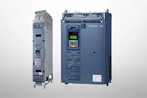
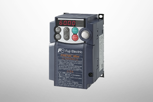
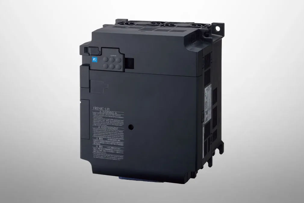
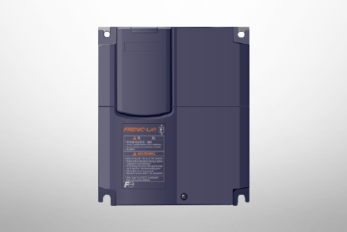
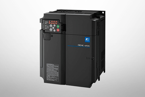
FRENIC-Lift (LM3U)
Specifications | Three-phase 400V
This model is not available in your region.
For more information regarding this product, please contact us via the inquiry form.
This model is not available in your region.
For more information regarding this product, please contact us via the inquiry form.
This model is not available in your region.
For more information regarding this product, please contact us via the inquiry form.
This model is not available in your region.
For more information regarding this product, please contact us via the inquiry form.


Three-phase 400V serie
-
Note 1
-
Standard applicable motors are for Fuji Electric's 4-pole standard motors.
-
Note 2
-
The rated capacity is for 400V series: 440V rating.
-
Note 3
-
A voltage higher than the power supply voltage cannot be output.
-
Note 4
-
Setting the carrier frequency (Function code: F26)to the following value or above requires current derating.
FRN0010 to 0018LM3U-4G, FRN0033LM3U-4G: 10 kHz(2 phase modulation)
FRN0027LM3U-4G and FRN0039LM3U-4G: 8 kHz
Select the unit's capacity so that the mean square current in operation is the following percentage or less of the unit's rated current.
The current derating (subtraction) is required in +45 to +50°C range
FRN0010LM3U-4G to FRN0018LM3U-4G, FRN0027LM3U-4G: 1.5% / °C
FRN0033LM3U-4G, FRN0039LM3U-4G: 1.0% / °C
-
Note 5
-
This is the estimated value when the power supply capacity is 500 kVA and connected to the power supply of %X=5%.
-
Note 6
-
Indicates the type with a DC reactor (DCR).
-
Note 7
-
Phase-to-phase imbalance ratio [%] = (Refer to max. voltage [V]-min. voltage [V])/3-phase averaging voltage [V] × 67(IEC/EN 61800-3)
Use an AC reactor (ACR: optional) when using with an unbalance ratio of 2 to 3%.
-
Note 8
-
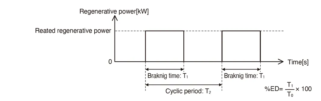
Braking time and braking duty ratio (%ED) are defined by cycling operation at the rated regenerative power shown in the diagram below.
-
Note 9
-
The allowable error of the minimum connectable resistance value is ±5%.
-
Note 10
-
Interval between overloads must be at least 1 second.
-
Note 11
-
Interval between overloads must be at least 9 second.
-
Note 12
-
The sum of power supply for car top board and brake power output must be less than or equal to the UPS power output capacity.
-
Note 13
-
If using Type 0027 or 0039, be sure to use a DC reactor (option).
-
Note 14
-
Applicable battery voltage range: 48V to 96V (nominal)
Please select a battery voltage equal to or higher than the value calculated by the following formula.
If used below that voltage, the deceleration torque and static torque may be insufficient.

If used below that voltage, the deceleration torque and static torque may be insufficient.
Also, if used at less than 72V, the continuous operating time may decrease.
-
Note 15
-
Phase control and cycle control have the following differences:
Phase control:
This method controls the voltage applied to the load from 0 to 100% by controlling the firing phase α every half cycle of the power supply frequency.

-
Note 16
-
Derating of output current relative to output voltage is as follows.
LM3U has 2 brake outputs.When the output is used in parallel, the current can be twice as large as the above.Consult us if overloading is required at the moment of excitation.

-
Note 17
-
If a voltage lower than the rated voltage is input, the output voltage may decrease to the equivalent of the input voltage
This model is not available in your region.
For more information regarding this product, please contact us via the inquiry form.
This model is not available in your region.
For more information regarding this product, please contact us via the inquiry form.
Column

Understanding application, benefits, basic structure, case study, types, and Fuji Electric's inverters with this video.
December 27,2021

Understanding the basics: Differences between inverters and converters
January 20,2021

How and what does an inverter take control of? A brief explanation to grasp the basic structure.
January 20,2021
The fundamentals of inverters and their uses.
January 20,2021