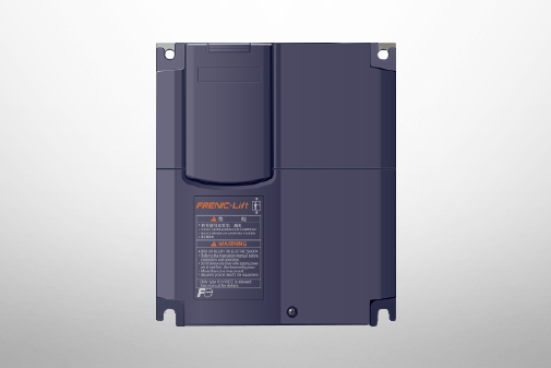
FRENIC-Lift (LM3S)
Standard Specifications | Single-phase 200V


-
Standard Specifications Single-phase 200V
Basic type (Single-phase 200V)
-
Note 1
-
Standard applicable motors are for Fuji Electric's 4-pole standard motors.
-
Note 2
-
The rated capacity is for 200V series: 220V rating.
-
Note 3
-
A voltage higher than the power supply voltage cannot be output.
-
Note 4
-
Indicates when the ambient temp. is 50°C 10kHz, the carrier frequency.
Select the inverter capacity so that the mean square current in operation is 80% or less of the inverter rated current.
-
Note 5
-
This is the estimated value when the power supply capacity is 500 kVA and connected to the power supply of %X=5%.
-
Note 6
-
Indicates the type with a DC reactor (DCR).
-
Note 7
-
Only braking operation can be used during battery operation. Cannot be used in load operation.
Connect UPS or battery power supply to L1/R,L3/T.
-
Note 8
-
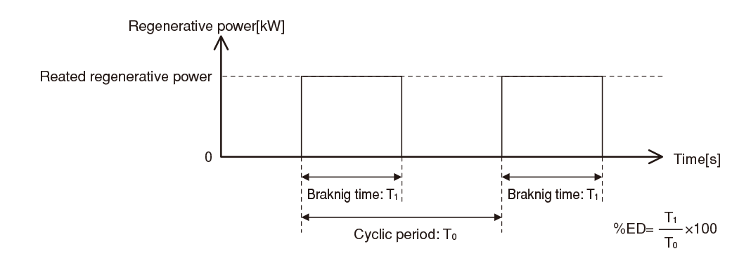
Braking time and braking duty ratio (%ED) are defined by cycling operation at the rated regenerative power shown
in the diagram below.

-
Note 9
-
The allowable error of the minimum connectable resistance value is ±5%.
-
Standard Specifications Single-phase 200V
Basic type (Single-phase 200V)
-
Note 1
-
Standard applicable motors are for Fuji Electric's 4-pole standard motors.
-
Note 2
-
The rated capacity is for 200V series: 220V rating.
-
Note 3
-
A voltage higher than the power supply voltage cannot be output.
-
Note 4
-
Indicates when the ambient temp. is 50°C 10kHz, the carrier frequency.
Select the inverter capacity so that the mean square current in operation is 80% or less of the inverter rated current.
-
Note 5
-
This is the estimated value when the power supply capacity is 500 kVA and connected to the power supply of %X=5%.
-
Note 6
-
Indicates the type with a DC reactor (DCR).
-
Note 7
-
Only braking operation can be used during battery operation. Cannot be used in load operation.
Connect UPS or battery power supply to L1/R,L3/T.
-
Note 8
-
Braking time and braking duty ratio (%ED) are defined by cycling operation at the rated regenerative power shown
in the diagram below.

-
Note 9
-
The allowable error of the minimum connectable resistance value is ±5%.
This model is not available in your region.
For more information regarding this product, please contact us via the inquiry form.
-
Standard Specifications Single-phase 200V
Basic type (Single-phase 200V)
-
Note 1
-
Standard applicable motors are for Fuji Electric's 4-pole standard motors.
-
Note 2
-
The rated capacity is for 200V series: 220V rating.
-
Note 3
-
A voltage higher than the power supply voltage cannot be output.
-
Note 4
-
Indicates when the ambient temp. is 50°C 10kHz, the carrier frequency.
Select the inverter capacity so that the mean square current in operation is 80% or less of the inverter rated current.
-
Note 5
-
This is the estimated value when the power supply capacity is 500 kVA and connected to the power supply of %X=5%.
-
Note 6
-
Indicates the type with a DC reactor (DCR).
-
Note 7
-
Only braking operation can be used during battery operation. Cannot be used in load operation.
Connect UPS or battery power supply to L1/R,L3/T.
-
Note 8
-
Braking time and braking duty ratio (%ED) are defined by cycling operation at the rated regenerative power shown
in the diagram below.

-
Note 9
-
The allowable error of the minimum connectable resistance value is ±5%.
-
Standard Specifications Single-phase 200V
Basic type (Single-phase 200V)
-
Note 1
-
Standard applicable motors are for Fuji Electric's 4-pole standard motors.
-
Note 2
-
The rated capacity is for 200V series: 220V rating.
-
Note 3
-
A voltage higher than the power supply voltage cannot be output.
-
Note 4
-
Indicates when the ambient temp. is 50°C 10kHz, the carrier frequency.
Select the inverter capacity so that the mean square current in operation is 80% or less of the inverter rated current.
-
Note 5
-
This is the estimated value when the power supply capacity is 500 kVA and connected to the power supply of %X=5%.
-
Note 6
-
Indicates the type with a DC reactor (DCR).
-
Note 7
-
Only braking operation can be used during battery operation. Cannot be used in load operation.
Connect UPS or battery power supply to L1/R,L3/T.
-
Note 8
-
Braking time and braking duty ratio (%ED) are defined by cycling operation at the rated regenerative power shown
in the diagram below.
-
Note 9
-
The allowable error of the minimum connectable resistance value is ±5%.
-
Standard Specifications Single-phase 200V
Basic type (Single-phase 200V)
-
Note 1
-
Standard applicable motors are for Fuji Electric's 4-pole standard motors.
-
Note 2
-
The rated capacity is for 200V series: 220V rating.
-
Note 3
-
A voltage higher than the power supply voltage cannot be output.
-
Note 4
-
Indicates when the ambient temp. is 50°C 10kHz, the carrier frequency.
Select the inverter capacity so that the mean square current in operation is 80% or less of the inverter rated current.
-
Note 5
-
This is the estimated value when the power supply capacity is 500 kVA and connected to the power supply of %X=5%.
-
Note 6
-
Indicates the type with a DC reactor (DCR).
-
Note 7
-
Only braking operation can be used during battery operation. Cannot be used in load operation.
Connect UPS or battery power supply to L1/R,L3/T.
-
Note 8
-
Braking time and braking duty ratio (%ED) are defined by cycling operation at the rated regenerative power shown
in the diagram below.

-
Note 9
-
The allowable error of the minimum connectable resistance value is ±5%.
AC Drives (Low Voltage) Support

Download documents
Column

Understanding application, benefits, basic structure, case study, types, and Fuji Electric's inverters with this video.
December 27,2021

Understanding the basics: Differences between inverters and converters
January 20,2021

How and what does an inverter take control of? A brief explanation to grasp the basic structure.
January 20,2021
The fundamentals of inverters and their uses.
January 20,2021