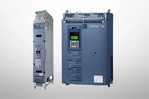
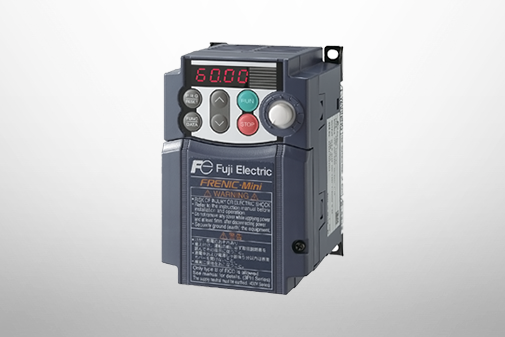
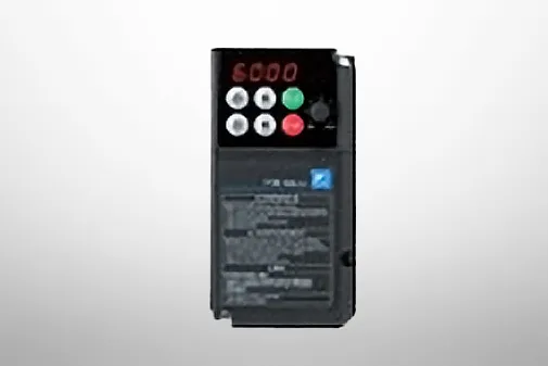
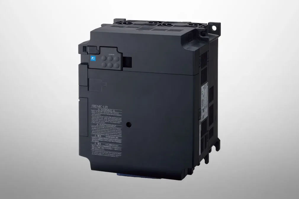
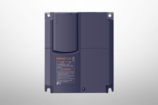
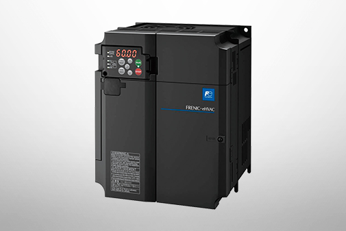
FRENIC-Lift (LM3S)
Specifications | Common Specifications


-
Common Specifications
-
Note 1
-
For test operation, such as feedback check of the encoder. Do not use with elevator control.
-
Note 2
-
Only during test run via "FRENIC Loader"
-
Note 1
-
These symbols are displayed on keypad LEDs.(Option for global only)
-
Note 2
-
○ Display is outputted to 30A,B,C. △ may not be displayed depending on the setting of the function code.
-
Note 1
-
These symbols are displayed on keypad LEDs.(Option for global only)
-
Note 2
-
○ Display is outputted to 30A,B,C. △ may not be displayed depending on the setting of the function code.
-
Note 3
-
PG wire break may not be detected.
| Item | Detailed specifications | ||
|---|---|---|---|
| Operating environment | Installation location | Indoors | |
| Ambient temperature | -10 to +55°C [14 to 131 °F] (current derating necessary in +50 to +55 °C [122 to 131 °F] range) Horizontal close mounting (22kW or less):-10 to +40°C [14 to 104 °F] |
||
| Ambient humidity | 5 to 95%RH (non-condensing) | ||
| Atmosphere | The inverter must not be exposed to dust, direct sunlight, corrosive or flammable gases, oil mist, vapor, water drops or vibration. (Pollution degree 2 (IEC60664-1)) The atmosphere must contain only a low level of salt. (0.01 mg/cm2 or less per year) There should be no condensation due to sudden temperature changes. |
||
| Altitude | 1000 m (3300 ft) or lower If used in a location with altitude of 1000 m (3300 ft) or higher, do so after reducing the output current as shown in the following table. 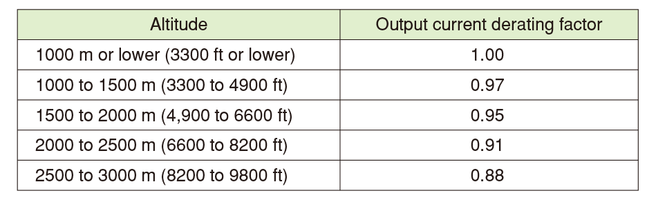 |
||
| Vibration | 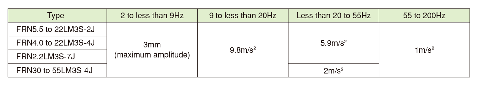 |
||
| Storage environment | Storage temperature (Note 1) | -25 to +70°C (during transport) (-13 to +158°F) | Places not subjected to condensation or freezing due to sudden temperature changes |
| -25 to +65°C (during temporary storage) (-13 to +149°F) | |||
| -10 to +35°C (during long-term storage) (14 to +95°F) | |||
| Relative humidity (Note 2) | During temporary storage: 5 to 95% RH (there should be no condensation) During long-term storage: 5 to 70% RH |
||
| Atmosphere | The inverter must not be exposed to dust, direct sunlight, corrosive or flammable gases, oil mist, vapor, water drops or vibration. The atmosphere must contain only a low level of salt. (0.01 mg/cm2 or less per year) |
||
| Atmospheric pressure | 86 to 106 kPa (during storage) 70 to 106 kPa (during transport) |
||
-
Note 1
-
Assuming comparatively short time storage, e.g., during transportation.
-
Note 2
-
Even if the humidity is within the specified requirements, avoid such places where the inverter will be subjected
to sudden changes in temperature that will cause condensation or freezing.
| Class | Symbol | Terminal name | Explanation | Remarks |
|---|---|---|---|---|
| Main circuit | L1/R,L2/S,L3/T | Main power supply input terminals | Connect a three-phase power supply. (3-phase models only) | |
| Connect a single-phase power supply. (single-phase models only) | ||||
| R0, T0 | Auxiliary control power input terminals | There is normally no need to use these terminals. If wishing to retain the integrated alarm signal issued if the protective function is triggered even when the inverter main power supply is cut off, or to constantly display the keypad, connect control power auxiliary input terminals to a power supply. If connecting a PWM converter, do not connect the power supply directly to the inverter control power auxiliary input terminals (R0, T0). |
FRN0076LM3S-2□ FRN0090LM3S-2□ FRN0031LM3S-4□ FRN0039LM3S-4□ | |
| U, V, W | Inverter output terminals | Connect three-phase motor terminals U, V, and W to match the phase sequence. | ||
| P1, P(+) | DC reactor connection terminals | Connect a DC reactor (DCR) (option) for power-factor improvement. | ||
| P(+), N(-) | DC link bus connection terminals | Connect braking unit terminals P(+) and N(-). Furthermore, DC link bus circuit of other inverters and PWM converters can be connected. | ||
| P(+), DB | Braking resistor connection terminals | Connect terminals P(+) and DB of the inverter to braking resistor terminals (option). | ||
| Inverter grounding terminal | This is a grounding terminal for the inverter chassis (case). Be sure to ground grounding terminals to ensure safety, and as a noise countermeasure. | |||
| Class | Symbol | Terminal name | Function |
|---|---|---|---|
| Analog input | [12] | Analog Set voltage input | (1) Specify the frequency based on the external voltage input. ・DC 0~±10V/0~±100(%) (2) Torque current command value and torque bias command other than speed setting by analog input It can be assigned and used. (3) Hardware Specifications (Note)Input impedance: 22(kΩ) Note: The maximum input is ±15 VDC, but is handled as ±10 VDC for voltages greater than ±10 VDC." |
| [11] | Analog Common | This is a common terminal of the analog input signal (terminal [12]). This terminal is isolated from terminals [CM] and [CMY]. |
|
| Digital input | [X1] | Digital Input 1 | (1) Various signals (free-run command, external alarm, multi-speed selection, etc.) can be set for terminals E01 to E07,E98,E99 can be set. (2) The input mode and SINK/SOURCE can be switched using SW1. (3) The operating mode between each digital input terminal and terminal [CM] can be switched to "ON when shorted (active ON)" or "OFF when shorted (active OFF)".  |
| [X2] | Digital Input 2 | ||
| [X3] | Digital Input 3 | ||
| [X4] | Digital Input 4 | ||
| [X5] | Digital Input 5 | ||
| [X6] | Digital Input 6 | ||
| [X7] | Digital Input 7 | ||
| [FWD] | Forward operation Stop command Input | ||
| [REV] | Reverse operation Stop command Input | ||
| [EN1] [EN2] |
Enable Input | (1) By opening the circuit between terminals [EN1] and [PLC], or between terminals [EN2] and [PLC], inverter output transistor operation is stopped by the IEC/EN 61800-5-2-compliant STO safety stop function. (2) The input mode for terminals [EN1] and [EN2] is fixed at SOURCE mode. (3)When this function is not used, short circuit between terminals [EN1]-[EN2]-[PLC].  |
|
| [PLC] | Programmable Controller Signal power | (1) Connect the output signal power supply for the programmable controller. (Rated voltage +24 VDC (power supply voltage fluctuation range: +20.4 to +27 VDC), maximum 100 mA DC) (2) The terminal can also be used as the power supply for loads connected to transistor outputs. |
|
| [CM] | Digital Common | This is a common terminal for digital input signals. The terminal is isolated from terminals [11] and [CMY] |
|
| Transistor output | [Y1] | Transistor output 1 | (1) Various signals (running signals, frequency arrival signals, overload early warning signals, etc.) set with function codes E20 to E22 can be output. (2) The operating mode between transistor output terminals [Y1],[Y2],[Y3] and terminal [CMY] can be switched to "ON when signal output (active ON)" or "OFF when signal output (active OFF)".  |
| [Y2] | Transistor output 2 | ||
| [Y3] | Transistor output 3 | ||
| [CMY] | Transistor output common | This is a common terminal for digital input signals. The terminal is insulated from terminals [11] and [CMY]. |
|
| Contact output | [Y5A] [Y5C] |
General contact output | (1) As a general contact output, various types of signals similar to the terminal [Y1] to [Y3] can be selected and output. Contact capacity: 250 VAC 0.3 A cosφ = 0.3, 48 VDC 0.5 A (2) The function code E24 selects and outputs a signal similar to that of the terminal [Y1][Y2][Y3]. (3) It is possible to switch between a "short circuit between terminals [Y5A] and [Y5C] when an ON signal is output (excitation: active ON)" or an "open circuit between terminals [Y5A] and [Y5C] when an ON signal is output (non-excitation: active OFF)". |
| [30A] [30B] [30C] |
Integrated alarm output | (1) When the inverter stops with an alarm, an integrated alarm is output at the relay contact (1C). Contact capacity: 250 VAC 0.3 A cosφ = 0.3, 48 VDC 0.5 A (2) The same signals as those of terminals [Y1] to [Y3] can be selected and output. (3) It is possible to switch between a "short circuit between terminals [30A] and [30C] when an ON signal is output (excitation: active ON)" or an "open circuit between terminals [30A] and [30C] when an ON signal is output (non-excitation: active OFF)". |
|
| Communication | RJ-45 Connector Keypad (Option only global model) |
RS-485 communication Port 1 (Keypad for connection) | (1) This is used as a connector for connecting the keypad(option only global model). The keypad power is supplied from the inverter via an extension cable for remote operation. To connect the keypad remotely, the keypad relay adapter CBAD-CP is required separately. (2) This is used to connect a personal computer or programmable controller, etc. by RS-485 communication after disconnecting the keypad. Protocols can be selected from the following. - Dedicated keypad protocol (automatically selected) - Modbus RTU, dedicated Fuji inverter protocols - Start-stop synchronization, half-duplex method - Max. communication distance: 20 m (when using RS-485 communication: 500 m) - Max. communication speed: 115.2 kbps(Note) Note: The communication speed when the engineering PC tool "FRENIC Loader 4" is connected is automatically adjusted. |
| USB Connector | USB port | This is a USB connector (miniB specification) for connecting to a personal computer. Function codes can be edited, transferred, or verified, an inverter test run can be carried out, and all states can be monitored using the engineering PC tool "FRENIC Loader 4". It is possible to edit, transfer, and verify the function code of "FRENIC Loader" with USB bus power. |
|
| Encoder(Note 1) | [PO] | Power supply for encoder | Power supply terminal for the encoder. ・Voltage specification :DC+5 V±10% ・Rated current: max.200mA |
| [CM] | Digital Common | Common terminal for encoder power supply. This terminal is isolated from terminals [11] and [CMY]. |
|
| [PA+] [PA-] | A phase input | A-phase input terminal for encoder. The frequency changes according to the motor speed. ・Input frequency:max.50 kHz ・Differential input-signal Vp-p:0.6~1.2V |
|
| [PB+] [PB-] | B phase input | B-phase input terminal for encoder. The frequency changes according to the motor speed. ・Input frequency:max.50 kHz ・Differential input-signal Vp-p:0.6~1.2V |
|
| [PB+] [PB-] | B phase input | B-phase input terminal for encoder. The frequency changes according to the motor speed. ・Input frequency:max.50 kHz ・Differential input-signal Vp-p:0.6~1.2V |
|
| [PC+] [PC-] | C phase input | C-phase input terminal for encoder. The frequency changes according to the motor speed. ・Input frequency:max.1 kHz ・Differential input-signal Vp-p:0.6~1.2V |
|
| [PD+] [PD-] | D phase input | D-phase input terminal for encoder. The frequency changes according to the motor speed. ・Input frequency:max.1 kHz ・Differential input-signal Vp-p:0.6~1.2V |
|
| [CK+] [CK-] | Communication clock for encoder | Clock output terminal for EnDat2.1 and BiSS protocol. | |
| [DT+] [DT-] | Communication data for encoder | Communication data I/O terminal is supported for EnDat2.1 and BiSS protocol. | |
| [SD] | ― | Do not connect to the shield cable of the encoder. | |
| [PAO] [PBO] |
A/B phase Pulse output | These terminals output the same frequency as A/B phase input. ・Output method: Open collector ・Output voltage :max.DC+27 V ・Output current :max.50 mA ・Output frequency: max.50kHz |
|
| [CM] | Digital Common | Common terminal for pulse output. This terminal is isolated from terminals [11] and [CMY]. |
-
Note 1
-
Encoder cable shall be max.20m.
-
Common Specifications
-
Note 1
-
For test operation, such as feedback check of the encoder. Do not use with elevator control.
-
Note 2
-
Only during test run via "FRENIC Loader"
-
Note 1
-
These symbols are displayed on keypad LEDs.(Option for global only)
-
Note 2
-
○ Display is outputted to 30A,B,C. △ may not be displayed depending on the setting of the function code.
-
Note 1
-
These symbols are displayed on keypad LEDs.(Option for global only)
-
Note 2
-
○ Display is outputted to 30A,B,C. △ may not be displayed depending on the setting of the function code.
-
Note 3
-
PG wire break may not be detected.
| Item | Detailed specifications | ||
|---|---|---|---|
| Operating environment | Installation location | Indoors | |
| Ambient temperature | -10 to +55°C [14 to 131 °F] (current derating necessary in +50 to +55 °C [122 to 131 °F] range) Horizontal close mounting (22kW or less):-10 to +40°C [14 to 104 °F] |
||
| Ambient humidity | 5 to 95%RH (non-condensing) | ||
| Atmosphere | The inverter must not be exposed to dust, direct sunlight, corrosive or flammable gases, oil mist, vapor, water drops or vibration. (Pollution degree 2 (IEC60664-1)) The atmosphere must contain only a low level of salt. (0.01 mg/cm2 or less per year) There should be no condensation due to sudden temperature changes. |
||
| Altitude | 1000 m (3300 ft) or lower If used in a location with altitude of 1000 m (3300 ft) or higher, do so after reducing the output current as shown in the following table. |
||
| Vibration | |
||
| Storage environment | Storage temperature (Note 1) | -25 to +70°C (during transport) (-13 to +158°F) | Places not subjected to condensation or freezing due to sudden temperature changes |
| -25 to +65°C (during temporary storage) (-13 to +149°F) | |||
| -10 to +35°C (during long-term storage) (14 to +95°F) | |||
| Relative humidity (Note 2) | During temporary storage: 5 to 95% RH (there should be no condensation) During long-term storage: 5 to 70% RH |
||
| Atmosphere | The inverter must not be exposed to dust, direct sunlight, corrosive or flammable gases, oil mist, vapor, water drops or vibration. The atmosphere must contain only a low level of salt. (0.01 mg/cm2 or less per year) |
||
| Atmospheric pressure | 86 to 106 kPa (during storage) 70 to 106 kPa (during transport) |
||
-
Note 1
-
Assuming comparatively short time storage, e.g., during transportation.
-
Note 2
-
Even if the humidity is within the specified requirements, avoid such places where the inverter will be subjected
to sudden changes in temperature that will cause condensation or freezing.
| Class | Symbol | Terminal name | Explanation | Remarks |
|---|---|---|---|---|
| Main circuit | L1/R,L2/S,L3/T | Main power supply input terminals | Connect a three-phase power supply. (3-phase models only) | |
| Connect a single-phase power supply. (single-phase models only) | ||||
| R0, T0 | Auxiliary control power input terminals | There is normally no need to use these terminals. If wishing to retain the integrated alarm signal issued if the protective function is triggered even when the inverter main power supply is cut off, or to constantly display the keypad, connect control power auxiliary input terminals to a power supply. If connecting a PWM converter, do not connect the power supply directly to the inverter control power auxiliary input terminals (R0, T0). |
FRN0076LM3S-2□ FRN0090LM3S-2□ FRN0031LM3S-4□ FRN0039LM3S-4□ | |
| U, V, W | Inverter output terminals | Connect three-phase motor terminals U, V, and W to match the phase sequence. | ||
| P1, P(+) | DC reactor connection terminals | Connect a DC reactor (DCR) (option) for power-factor improvement. | ||
| P(+), N(-) | DC link bus connection terminals | Connect braking unit terminals P(+) and N(-). Furthermore, DC link bus circuit of other inverters and PWM converters can be connected. | ||
| P(+), DB | Braking resistor connection terminals | Connect terminals P(+) and DB of the inverter to braking resistor terminals (option). | ||
| Inverter grounding terminal | This is a grounding terminal for the inverter chassis (case). Be sure to ground grounding terminals to ensure safety, and as a noise countermeasure. | |||
| Class | Symbol | Terminal name | Function |
|---|---|---|---|
| Analog input | [12] | Analog Set voltage input | (1) Specify the frequency based on the external voltage input. ・DC 0~±10V/0~±100(%) (2) Torque current command value and torque bias command other than speed setting by analog input It can be assigned and used. (3) Hardware Specifications (Note)Input impedance: 22(kΩ) Note: The maximum input is ±15 VDC, but is handled as ±10 VDC for voltages greater than ±10 VDC." |
| [11] | Analog Common | This is a common terminal of the analog input signal (terminal [12]). This terminal is isolated from terminals [CM] and [CMY]. |
|
| Digital input | [X1] | Digital Input 1 | (1) Various signals (free-run command, external alarm, multi-speed selection, etc.) can be set for terminals E01 to E07,E98,E99 can be set. (2) The input mode and SINK/SOURCE can be switched using SW1. (3) The operating mode between each digital input terminal and terminal [CM] can be switched to "ON when shorted (active ON)" or "OFF when shorted (active OFF)". |
| [X2] | Digital Input 2 | ||
| [X3] | Digital Input 3 | ||
| [X4] | Digital Input 4 | ||
| [X5] | Digital Input 5 | ||
| [X6] | Digital Input 6 | ||
| [X7] | Digital Input 7 | ||
| [FWD] | Forward operation Stop command Input | ||
| [REV] | Reverse operation Stop command Input | ||
| [EN1] [EN2] |
Enable Input | (1) By opening the circuit between terminals [EN1] and [PLC], or between terminals [EN2] and [PLC], inverter output transistor operation is stopped by the IEC/EN 61800-5-2-compliant STO safety stop function. (2) The input mode for terminals [EN1] and [EN2] is fixed at SOURCE mode. (3)When this function is not used, short circuit between terminals [EN1]-[EN2]-[PLC]. |
|
| [PLC] | Programmable Controller Signal power | (1) Connect the output signal power supply for the programmable controller. (Rated voltage +24 VDC (power supply voltage fluctuation range: +20.4 to +27 VDC), maximum 100 mA DC) (2) The terminal can also be used as the power supply for loads connected to transistor outputs. |
|
| [CM] | Digital Common | This is a common terminal for digital input signals. The terminal is isolated from terminals [11] and [CMY] |
|
| Transistor output | [Y1] | Transistor output 1 | (1) Various signals (running signals, frequency arrival signals, overload early warning signals, etc.) set with function codes E20 to E22 can be output. (2) The operating mode between transistor output terminals [Y1],[Y2],[Y3] and terminal [CMY] can be switched to "ON when signal output (active ON)" or "OFF when signal output (active OFF)". |
| [Y2] | Transistor output 2 | ||
| [Y3] | Transistor output 3 | ||
| [CMY] | Transistor output common | This is a common terminal for digital input signals. The terminal is isolated from terminals [11] and [CMY]. |
|
| Contact output | [Y5A] [Y5C] |
General contact output | (1) As a general contact output, various types of signals similar to the terminal [Y1] to [Y3] can be selected and output. Contact capacity: 250 VAC 0.3 A cosφ = 0.3, 48 VDC 0.5 A (2) The function code E24 selects and outputs a signal similar to that of the terminal [Y1][Y2][Y3]. (3) It is possible to switch between a "short circuit between terminals [Y5A] and [Y5C] when an ON signal is output (excitation: active ON)" or an "open circuit between terminals [Y5A] and [Y5C] when an ON signal is output (non-excitation: active OFF)". |
| [30A] [30B] [30C] |
Integrated alarm output | (1) When the inverter stops with an alarm, an integrated alarm is output at the relay contact (1C). Contact capacity: 250 VAC 0.3 A cosφ = 0.3, 48 VDC 0.5 A (2) The same signals as those of terminals [Y1] to [Y3] can be selected and output. (3) It is possible to switch between a "short circuit between terminals [30A] and [30C] when an ON signal is output (excitation: active ON)" or an "open circuit between terminals [30A] and [30C] when an ON signal is output (non-excitation: active OFF)". |
|
| Communication | RJ-45 Connector Keypad (Option only global model) |
RS-485 communication Port 1 (Keypad for connection) | (1) This is used as a connector for connecting the keypad(option only global model). The keypad power is supplied from the inverter via an extension cable for remote operation. To connect the keypad remotely, the keypad relay adapter CBAD-CP is required separately. (2) This is used to connect a personal computer or programmable controller, etc. by RS-485 communication after disconnecting the keypad. Protocols can be selected from the following. - Dedicated keypad protocol (automatically selected) - Modbus RTU, dedicated Fuji inverter protocols - Start-stop synchronization, half-duplex method - Max. communication distance: 20 m (when using RS-485 communication: 500 m) - Max. communication speed: 115.2 kbps(Note) Note: The communication speed when the engineering PC tool "FRENIC Loader 4" is connected is automatically adjusted. |
| USB Connector | USB port | This is a USB connector (miniB specification) for connecting to a personal computer. Function codes can be edited, transferred, or verified, an inverter test run can be carried out, and all states can be monitored using the engineering PC tool "FRENIC Loader 4". It is possible to edit, transfer, and verify the function code of "FRENIC Loader" with USB bus power. |
|
| Encoder(Note 1) | [PO] | Power supply for encoder | Power supply terminal for the encoder. ・Voltage specification :DC+5 V±10% ・Rated current: max.200mA |
| [CM] | Digital Common | Common terminal for encoder power supply. This terminal is isolated from terminals [11] and [CMY]. |
|
| [PA+] [PA-] | A phase input | A-phase input terminal for encoder. The frequency changes according to the motor speed. ・Input frequency:max.50 kHz ・Differential input-signal Vp-p:0.6~1.2V |
|
| [PB+] [PB-] | B phase input | B-phase input terminal for encoder. The frequency changes according to the motor speed. ・Input frequency:max.50 kHz ・Differential input-signal Vp-p:0.6~1.2V |
|
| [PB+] [PB-] | B phase input | B-phase input terminal for encoder. The frequency changes according to the motor speed. ・Input frequency:max.50 kHz ・Differential input-signal Vp-p:0.6~1.2V |
|
| [PC+] [PC-] | C phase input | C-phase input terminal for encoder. The frequency changes according to the motor speed. ・Input frequency:max.1 kHz ・Differential input-signal Vp-p:0.6~1.2V |
|
| [PD+] [PD-] | D phase input | D-phase input terminal for encoder. The frequency changes according to the motor speed. ・Input frequency:max.1 kHz ・Differential input-signal Vp-p:0.6~1.2V |
|
| [CK+] [CK-] | Communication clock for encoder | Clock output terminal for EnDat2.1 and BiSS protocol. | |
| [DT+] [DT-] | Communication data for encoder | Communication data I/O terminal is supported for EnDat2.1 and BiSS protocol. | |
| [SD] | ― | Do not connect to the shield cable of the encoder. | |
| [PAO] [PBO] |
A/B phase Pulse output | These terminals output the same frequency as A/B phase input. ・Output method: Open collector ・Output voltage :max.DC+27 V ・Output current :max.50 mA ・Output frequency: max.50kHz |
|
| [CM] | Digital Common | Common terminal for pulse output. This terminal is isolated from terminals [11] and [CMY]. |
-
Note 1
-
Encoder cable shall be max.20m.
-
Common Specifications
-
Note 1
-
For test operation, such as feedback check of the encoder. Do not use with elevator control.
-
Note 2
-
Only during test run via "FRENIC Loader"
-
Note 1
-
These symbols are displayed on keypad LEDs.(Option for global only)
-
Note 2
-
○ Display is outputted to 30A,B,C. △ may not be displayed depending on the setting of the function code.
-
Note 1
-
These symbols are displayed on keypad LEDs.(Option for global only)
-
Note 2
-
○ Display is outputted to 30A,B,C. △ may not be displayed depending on the setting of the function code.
-
Note 3
-
PG wire break may not be detected.
| Item | Detailed specifications | ||
|---|---|---|---|
| Operating environment | Installation location | Indoors | |
| Ambient temperature | -10 to +55°C [14 to 131 °F] (current derating necessary in +50 to +55 °C [122 to 131 °F] range) Horizontal close mounting (22kW or less):-10 to +40°C [14 to 104 °F] |
||
| Ambient humidity | 5 to 95%RH (non-condensing) | ||
| Atmosphere | The inverter must not be exposed to dust, direct sunlight, corrosive or flammable gases, oil mist, vapor, water drops or vibration. (Pollution degree 2 (IEC60664-1)) The atmosphere must contain only a low level of salt. (0.01 mg/cm2 or less per year) There should be no condensation due to sudden temperature changes. |
||
| Altitude | 1000 m (3300 ft) or lower If used in a location with altitude of 1000 m (3300 ft) or higher, do so after reducing the output current as shown in the following table. |
||
| Vibration | |
||
| Storage environment | Storage temperature (Note 1) | -25 to +70°C (during transport) (-13 to +158°F) | Places not subjected to condensation or freezing due to sudden temperature changes |
| -25 to +65°C (during temporary storage) (-13 to +149°F) | |||
| -10 to +35°C (during long-term storage) (14 to +95°F) | |||
| Relative humidity (Note 2) | During temporary storage: 5 to 95% RH (there should be no condensation) During long-term storage: 5 to 70% RH |
||
| Atmosphere | The inverter must not be exposed to dust, direct sunlight, corrosive or flammable gases, oil mist, vapor, water drops or vibration. The atmosphere must contain only a low level of salt. (0.01 mg/cm2 or less per year) |
||
| Atmospheric pressure | 86 to 106 kPa (during storage) 70 to 106 kPa (during transport) |
||
-
Note 1
-
Assuming comparatively short time storage, e.g., during transportation.
-
Note 2
-
Even if the humidity is within the specified requirements, avoid such places where the inverter will be subjected
to sudden changes in temperature that will cause condensation or freezing.
| Class | Symbol | Terminal name | Explanation | Remarks |
|---|---|---|---|---|
| Main circuit | L1/R,L2/S,L3/T | Main power supply input terminals | Connect a three-phase power supply. (3-phase models only) | |
| Connect a single-phase power supply. (single-phase models only) | ||||
| R0, T0 | Auxiliary control power input terminals | There is normally no need to use these terminals. If wishing to retain the integrated alarm signal issued if the protective function is triggered even when the inverter main power supply is cut off, or to constantly display the keypad, connect control power auxiliary input terminals to a power supply. If connecting a PWM converter, do not connect the power supply directly to the inverter control power auxiliary input terminals (R0, T0). |
FRN0076LM3S-2□ FRN0090LM3S-2□ FRN0031LM3S-4□ FRN0039LM3S-4□ | |
| U, V, W | Inverter output terminals | Connect three-phase motor terminals U, V, and W to match the phase sequence. | ||
| P1, P(+) | DC reactor connection terminals | Connect a DC reactor (DCR) (option) for power-factor improvement. | ||
| P(+), N(-) | DC link bus connection terminals | Connect braking unit terminals P(+) and N(-). Furthermore, DC link bus circuit of other inverters and PWM converters can be connected. | ||
| P(+), DB | Braking resistor connection terminals | Connect terminals P(+) and DB of the inverter to braking resistor terminals (option). | ||
| Inverter grounding terminal | This is a grounding terminal for the inverter chassis (case). Be sure to ground grounding terminals to ensure safety, and as a noise countermeasure. | |||
| Class | Symbol | Terminal name | Function |
|---|---|---|---|
| Analog input | [12] | Analog Set voltage input | (1) Specify the frequency based on the external voltage input. ・DC 0~±10V/0~±100(%) (2) Torque current command value and torque bias command other than speed setting by analog input It can be assigned and used. (3) Hardware Specifications (Note)Input impedance: 22(kΩ) Note: The maximum input is ±15 VDC, but is handled as ±10 VDC for voltages greater than ±10 VDC." |
| [11] | Analog Common | This is a common terminal of the analog input signal (terminal [12]). This terminal is isolated from terminals [CM] and [CMY]. |
|
| Digital input | [X1] | Digital Input 1 | (1) Various signals (free-run command, external alarm, multi-speed selection, etc.) can be set for terminals E01 to E07,E98,E99 can be set. (2) The input mode and SINK/SOURCE can be switched using SW1. (3) The operating mode between each digital input terminal and terminal [CM] can be switched to "ON when shorted (active ON)" or "OFF when shorted (active OFF)". |
| [X2] | Digital Input 2 | ||
| [X3] | Digital Input 3 | ||
| [X4] | Digital Input 4 | ||
| [X5] | Digital Input 5 | ||
| [X6] | Digital Input 6 | ||
| [X7] | Digital Input 7 | ||
| [FWD] | Forward operation Stop command Input | ||
| [REV] | Reverse operation Stop command Input | ||
| [EN1] [EN2] |
Enable Input | (1) By opening the circuit between terminals [EN1] and [PLC], or between terminals [EN2] and [PLC], inverter output transistor operation is stopped by the IEC/EN 61800-5-2-compliant STO safety stop function. (2) The input mode for terminals [EN1] and [EN2] is fixed at SOURCE mode. (3)When this function is not used, short circuit between terminals [EN1]-[EN2]-[PLC]. |
|
| [PLC] | Programmable Controller Signal power | (1) Connect the output signal power supply for the programmable controller. (Rated voltage +24 VDC (power supply voltage fluctuation range: +20.4 to +27 VDC), maximum 100 mA DC) (2) The terminal can also be used as the power supply for loads connected to transistor outputs. |
|
| [CM] | Digital Common | This is a common terminal for digital input signals. The terminal is isolated from terminals [11] and [CMY] |
|
| Transistor output | [Y1] | Transistor output 1 | (1) Various signals (running signals, frequency arrival signals, overload early warning signals, etc.) set with function codes E20 to E22 can be output. (2) The operating mode between transistor output terminals [Y1],[Y2],[Y3] and terminal [CMY] can be switched to "ON when signal output (active ON)" or "OFF when signal output (active OFF)". |
| [Y2] | Transistor output 2 | ||
| [Y3] | Transistor output 3 | ||
| [CMY] | Transistor output common | This is a common terminal for digital input signals. The terminal is insulated from terminals [11] and [CMY]. |
|
| Contact output | [Y5A] [Y5C] |
General contact output | (1) As a general contact output, various types of signals similar to the terminal [Y1] to [Y3] can be selected and output. Contact capacity: 250 VAC 0.3 A cosφ = 0.3, 48 VDC 0.5 A (2) The function code E24 selects and outputs a signal similar to that of the terminal [Y1][Y2][Y3]. (3) It is possible to switch between a "short circuit between terminals [Y5A] and [Y5C] when an ON signal is output (excitation: active ON)" or an "open circuit between terminals [Y5A] and [Y5C] when an ON signal is output (non-excitation: active OFF)". |
| [30A] [30B] [30C] |
Integrated alarm output | (1) When the inverter stops with an alarm, an integrated alarm is output at the relay contact (1C). Contact capacity: 250 VAC 0.3 A cosφ = 0.3, 48 VDC 0.5 A (2) The same signals as those of terminals [Y1] to [Y3] can be selected and output. (3) It is possible to switch between a "short circuit between terminals [30A] and [30C] when an ON signal is output (excitation: active ON)" or an "open circuit between terminals [30A] and [30C] when an ON signal is output (non-excitation: active OFF)". |
|
| Communication | RJ-45 Connector Keypad (Option only global model) |
RS-485 communication Port 1 (Keypad for connection) | (1) This is used as a connector for connecting the keypad(option only global model). The keypad power is supplied from the inverter via an extension cable for remote operation. To connect the keypad remotely, the keypad relay adapter CBAD-CP is required separately. (2) This is used to connect a personal computer or programmable controller, etc. by RS-485 communication after disconnecting the keypad. Protocols can be selected from the following. - Dedicated keypad protocol (automatically selected) - Modbus RTU, dedicated Fuji inverter protocols - Start-stop synchronization, half-duplex method - Max. communication distance: 20 m (when using RS-485 communication: 500 m) - Max. communication speed: 115.2 kbps(Note) Note: The communication speed when the engineering PC tool "FRENIC Loader 4" is connected is automatically adjusted. |
| USB Connector | USB port | This is a USB connector (miniB specification) for connecting to a personal computer. Function codes can be edited, transferred, or verified, an inverter test run can be carried out, and all states can be monitored using the engineering PC tool "FRENIC Loader 4". It is possible to edit, transfer, and verify the function code of "FRENIC Loader" with USB bus power. |
|
| Encoder(Note 1) | [PO] | Power supply for encoder | Power supply terminal for the encoder. ・Voltage specification :DC+5 V±10% ・Rated current: max.200mA |
| [CM] | Digital Common | Common terminal for encoder power supply. This terminal is isolated from terminals [11] and [CMY]. |
|
| [PA+] [PA-] | A phase input | A-phase input terminal for encoder. The frequency changes according to the motor speed. ・Input frequency:max.50 kHz ・Differential input-signal Vp-p:0.6~1.2V |
|
| [PB+] [PB-] | B phase input | B-phase input terminal for encoder. The frequency changes according to the motor speed. ・Input frequency:max.50 kHz ・Differential input-signal Vp-p:0.6~1.2V |
|
| [PB+] [PB-] | B phase input | B-phase input terminal for encoder. The frequency changes according to the motor speed. ・Input frequency:max.50 kHz ・Differential input-signal Vp-p:0.6~1.2V |
|
| [PC+] [PC-] | C phase input | C-phase input terminal for encoder. The frequency changes according to the motor speed. ・Input frequency:max.1 kHz ・Differential input-signal Vp-p:0.6~1.2V |
|
| [PD+] [PD-] | D phase input | D-phase input terminal for encoder. The frequency changes according to the motor speed. ・Input frequency:max.1 kHz ・Differential input-signal Vp-p:0.6~1.2V |
|
| [CK+] [CK-] | Communication clock for encoder | Clock output terminal for EnDat2.1 and BiSS protocol. | |
| [DT+] [DT-] | Communication data for encoder | Communication data I/O terminal is supported for EnDat2.1 and BiSS protocol. | |
| [SD] | ― | Do not connect to the shield cable of the encoder. | |
| [PAO] [PBO] |
A/B phase Pulse output | These terminals output the same frequency as A/B phase input. ・Output method: Open collector ・Output voltage :max.DC+27 V ・Output current :max.50 mA ・Output frequency: max.50kHz |
|
| [CM] | Digital Common | Common terminal for pulse output. This terminal is isolated from terminals [11] and [CMY]. |
-
Note 1
-
Encoder cable shall be max.20m.
This model is not available in your region.
For more information regarding this product, please contact us via the inquiry form.
-
Common Specifications
-
Note 1
-
For test operation, such as feedback check of the encoder. Do not use with elevator control.
-
Note 2
-
Only during test run via "FRENIC Loader"
-
Note 1
-
These symbols are displayed on keypad LEDs.(Option for global only)
-
Note 2
-
○ Display is outputted to 30A,B,C. △ may not be displayed depending on the setting of the function code.
-
Note 1
-
These symbols are displayed on keypad LEDs.(Option for global only)
-
Note 2
-
○ Display is outputted to 30A,B,C. △ may not be displayed depending on the setting of the function code.
-
Note 3
-
PG wire break may not be detected.
| Item | Detailed specifications | ||
|---|---|---|---|
| Operating environment | Installation location | Indoors | |
| Ambient temperature | -10 to +55°C [14 to 131 °F] (current derating necessary in +50 to +55 °C [122 to 131 °F] range) Horizontal close mounting (22kW or less):-10 to +40°C [14 to 104 °F] |
||
| Ambient humidity | 5 to 95%RH (non-condensing) | ||
| Atmosphere | The inverter must not be exposed to dust, direct sunlight, corrosive or flammable gases, oil mist, vapor, water drops or vibration. (Pollution degree 2 (IEC60664-1)) The atmosphere must contain only a low level of salt. (0.01 mg/cm2 or less per year) There should be no condensation due to sudden temperature changes. |
||
| Altitude | 1000 m (3300 ft) or lower If used in a location with altitude of 1000 m (3300 ft) or higher, do so after reducing the output current as shown in the following table. |
||
| Vibration | |
||
| Storage environment | Storage temperature (Note 1) | -25 to +70°C (during transport) (-13 to +158°F) | Places not subjected to condensation or freezing due to sudden temperature changes |
| -25 to +65°C (during temporary storage) (-13 to +149°F) | |||
| -10 to +35°C (during long-term storage) (14 to +95°F) | |||
| Relative humidity (Note 2) | During temporary storage: 5 to 95% RH (there should be no condensation) During long-term storage: 5 to 70% RH |
||
| Atmosphere | The inverter must not be exposed to dust, direct sunlight, corrosive or flammable gases, oil mist, vapor, water drops or vibration. The atmosphere must contain only a low level of salt. (0.01 mg/cm2 or less per year) |
||
| Atmospheric pressure | 86 to 106 kPa (during storage) 70 to 106 kPa (during transport) |
||
-
Note 1
-
Assuming comparatively short time storage, e.g., during transportation.
-
Note 2
-
Even if the humidity is within the specified requirements, avoid such places where the inverter will be subjected
to sudden changes in temperature that will cause condensation or freezing.
| Class | Symbol | Terminal name | Explanation | Remarks |
|---|---|---|---|---|
| Main circuit | L1/R,L2/S,L3/T | Main power supply input terminals | Connect a three-phase power supply. (3-phase models only) | |
| Connect a single-phase power supply. (single-phase models only) | ||||
| R0, T0 | Auxiliary control power input terminals | There is normally no need to use these terminals. If wishing to retain the integrated alarm signal issued if the protective function is triggered even when the inverter main power supply is cut off, or to constantly display the keypad, connect control power auxiliary input terminals to a power supply. If connecting a PWM converter, do not connect the power supply directly to the inverter control power auxiliary input terminals (R0, T0). |
FRN0076LM3S-2□ FRN0090LM3S-2□ FRN0031LM3S-4□ FRN0039LM3S-4□ | |
| U, V, W | Inverter output terminals | Connect three-phase motor terminals U, V, and W to match the phase sequence. | ||
| P1, P(+) | DC reactor connection terminals | Connect a DC reactor (DCR) (option) for power-factor improvement. | ||
| P(+), N(-) | DC link bus connection terminals | Connect braking unit terminals P(+) and N(-). Furthermore, DC link bus circuit of other inverters and PWM converters can be connected. | ||
| P(+), DB | Braking resistor connection terminals | Connect terminals P(+) and DB of the inverter to braking resistor terminals (option). | ||
| Inverter grounding terminal | This is a grounding terminal for the inverter chassis (case). Be sure to ground grounding terminals to ensure safety, and as a noise countermeasure. | |||
| Class | Symbol | Terminal name | Function |
|---|---|---|---|
| Analog input | [12] | Analog Set voltage input | (1) Specify the frequency based on the external voltage input. ・DC 0~±10V/0~±100(%) (2) Torque current command value and torque bias command other than speed setting by analog input It can be assigned and used. (3) Hardware Specifications (Note)Input impedance: 22(kΩ) Note: The maximum input is ±15 VDC, but is handled as ±10 VDC for voltages greater than ±10 VDC." |
| [11] | Analog Common | This is a common terminal of the analog input signal (terminal [12]). This terminal is isolated from terminals [CM] and [CMY]. |
|
| Digital input | [X1] | Digital Input 1 | (1) Various signals (free-run command, external alarm, multi-speed selection, etc.) can be set for terminals E01 to E07,E98,E99 can be set. (2) The input mode and SINK/SOURCE can be switched using SW1. (3) The operating mode between each digital input terminal and terminal [CM] can be switched to "ON when shorted (active ON)" or "OFF when shorted (active OFF)". |
| [X2] | Digital Input 2 | ||
| [X3] | Digital Input 3 | ||
| [X4] | Digital Input 4 | ||
| [X5] | Digital Input 5 | ||
| [X6] | Digital Input 6 | ||
| [X7] | Digital Input 7 | ||
| [FWD] | Forward operation Stop command Input | ||
| [REV] | Reverse operation Stop command Input | ||
| [EN1] [EN2] |
Enable Input | (1) By opening the circuit between terminals [EN1] and [PLC], or between terminals [EN2] and [PLC], inverter output transistor operation is stopped by the IEC/EN 61800-5-2-compliant STO safety stop function. (2) The input mode for terminals [EN1] and [EN2] is fixed at SOURCE mode. (3)When this function is not used, short circuit between terminals [EN1]-[EN2]-[PLC]. |
|
| [PLC] | Programmable Controller Signal power | (1) Connect the output signal power supply for the programmable controller. (Rated voltage +24 VDC (power supply voltage fluctuation range: +20.4 to +27 VDC), maximum 100 mA DC) (2) The terminal can also be used as the power supply for loads connected to transistor outputs. |
|
| [CM] | Digital Common | This is a common terminal for digital input signals. The terminal is isolated from terminals [11] and [CMY] |
|
| Transistor output | [Y1] | Transistor output 1 | (1) Various signals (running signals, frequency arrival signals, overload early warning signals, etc.) set with function codes E20 to E22 can be output. (2) The operating mode between transistor output terminals [Y1],[Y2],[Y3] and terminal [CMY] can be switched to "ON when signal output (active ON)" or "OFF when signal output (active OFF)". |
| [Y2] | Transistor output 2 | ||
| [Y3] | Transistor output 3 | ||
| [CMY] | Transistor output common | This is a common terminal for digital input signals. The terminal is isolated from terminals [11] and [CMY]. |
|
| Contact output | [Y5A] [Y5C] |
General contact output | (1) As a general contact output, various types of signals similar to the terminal [Y1] to [Y3] can be selected and output. Contact capacity: 250 VAC 0.3 A cosφ = 0.3, 48 VDC 0.5 A (2) The function code E24 selects and outputs a signal similar to that of the terminal [Y1][Y2][Y3]. (3) It is possible to switch between a "short circuit between terminals [Y5A] and [Y5C] when an ON signal is output (excitation: active ON)" or an "open circuit between terminals [Y5A] and [Y5C] when an ON signal is output (non-excitation: active OFF)". |
| [30A] [30B] [30C] |
Integrated alarm output | (1) When the inverter stops with an alarm, an integrated alarm is output at the relay contact (1C). Contact capacity: 250 VAC 0.3 A cosφ = 0.3, 48 VDC 0.5 A (2) The same signals as those of terminals [Y1] to [Y3] can be selected and output. (3) It is possible to switch between a "short circuit between terminals [30A] and [30C] when an ON signal is output (excitation: active ON)" or an "open circuit between terminals [30A] and [30C] when an ON signal is output (non-excitation: active OFF)". |
|
| Communication | RJ-45 Connector Keypad (Option only global model) |
RS-485 communication Port 1 (Keypad for connection) | (1) This is used as a connector for connecting the keypad(option only global model). The keypad power is supplied from the inverter via an extension cable for remote operation. To connect the keypad remotely, the keypad relay adapter CBAD-CP is required separately. (2) This is used to connect a personal computer or programmable controller, etc. by RS-485 communication after disconnecting the keypad. Protocols can be selected from the following. - Dedicated keypad protocol (automatically selected) - Modbus RTU, dedicated Fuji inverter protocols - Start-stop synchronization, half-duplex method - Max. communication distance: 20 m (when using RS-485 communication: 500 m) - Max. communication speed: 115.2 kbps(Note) Note: The communication speed when the engineering PC tool "FRENIC Loader 4" is connected is automatically adjusted. |
| USB Connector | USB port | This is a USB connector (miniB specification) for connecting to a personal computer. Function codes can be edited, transferred, or verified, an inverter test run can be carried out, and all states can be monitored using the engineering PC tool "FRENIC Loader 4". It is possible to edit, transfer, and verify the function code of "FRENIC Loader" with USB bus power. |
|
| Encoder(Note 1) | [PO] | Power supply for encoder | Power supply terminal for the encoder. ・Voltage specification :DC+5 V±10% ・Rated current: max.200mA |
| [CM] | Digital Common | Common terminal for encoder power supply. This terminal is isolated from terminals [11] and [CMY]. |
|
| [PA+] [PA-] | A phase input | A-phase input terminal for encoder. The frequency changes according to the motor speed. ・Input frequency:max.50 kHz ・Differential input-signal Vp-p:0.6~1.2V |
|
| [PB+] [PB-] | B phase input | B-phase input terminal for encoder. The frequency changes according to the motor speed. ・Input frequency:max.50 kHz ・Differential input-signal Vp-p:0.6~1.2V |
|
| [PB+] [PB-] | B phase input | B-phase input terminal for encoder. The frequency changes according to the motor speed. ・Input frequency:max.50 kHz ・Differential input-signal Vp-p:0.6~1.2V |
|
| [PC+] [PC-] | C phase input | C-phase input terminal for encoder. The frequency changes according to the motor speed. ・Input frequency:max.1 kHz ・Differential input-signal Vp-p:0.6~1.2V |
|
| [PD+] [PD-] | D phase input | D-phase input terminal for encoder. The frequency changes according to the motor speed. ・Input frequency:max.1 kHz ・Differential input-signal Vp-p:0.6~1.2V |
|
| [CK+] [CK-] | Communication clock for encoder | Clock output terminal for EnDat2.1 and BiSS protocol. | |
| [DT+] [DT-] | Communication data for encoder | Communication data I/O terminal is supported for EnDat2.1 and BiSS protocol. | |
| [SD] | ― | Do not connect to the shield cable of the encoder. | |
| [PAO] [PBO] |
A/B phase Pulse output | These terminals output the same frequency as A/B phase input. ・Output method: Open collector ・Output voltage :max.DC+27 V ・Output current :max.50 mA ・Output frequency: max.50kHz |
|
| [CM] | Digital Common | Common terminal for pulse output. This terminal is isolated from terminals [11] and [CMY]. |
-
Note 1
-
Encoder cable shall be max.20m.
-
Common Specifications
-
Note 1
-
For test operation, such as feedback check of the encoder. Do not use with elevator control.
-
Note 2
-
Only during test run via "FRENIC Loader"
-
Note 1
-
These symbols are displayed on keypad LEDs.(Option for global only)
-
Note 2
-
○ Display is outputted to 30A,B,C. △ may not be displayed depending on the setting of the function code.
-
Note 1
-
These symbols are displayed on keypad LEDs.(Option for global only)
-
Note 2
-
○ Display is outputted to 30A,B,C. △ may not be displayed depending on the setting of the function code.
-
Note 3
-
PG wire break may not be detected.
| Item | Detailed specifications | ||
|---|---|---|---|
| Operating environment | Installation location | Indoors | |
| Ambient temperature | -10 to +55°C [14 to 131 °F] (current derating necessary in +50 to +55 °C [122 to 131 °F] range) Horizontal close mounting (22kW or less):-10 to +40°C [14 to 104 °F] |
||
| Ambient humidity | 5 to 95%RH (non-condensing) | ||
| Atmosphere | The inverter must not be exposed to dust, direct sunlight, corrosive or flammable gases, oil mist, vapor, water drops or vibration. (Pollution degree 2 (IEC60664-1)) The atmosphere must contain only a low level of salt. (0.01 mg/cm2 or less per year) There should be no condensation due to sudden temperature changes. |
||
| Altitude | 1000 m (3300 ft) or lower If used in a location with altitude of 1000 m (3300 ft) or higher, do so after reducing the output current as shown in the following table. |
||
| Vibration | |
||
| Storage environment | Storage temperature (Note 1) | -25 to +70°C (during transport) (-13 to +158°F) | Places not subjected to condensation or freezing due to sudden temperature changes |
| -25 to +65°C (during temporary storage) (-13 to +149°F) | |||
| -10 to +35°C (during long-term storage) (14 to +95°F) | |||
| Relative humidity (Note 2) | During temporary storage: 5 to 95% RH (there should be no condensation) During long-term storage: 5 to 70% RH |
||
| Atmosphere | The inverter must not be exposed to dust, direct sunlight, corrosive or flammable gases, oil mist, vapor, water drops or vibration. The atmosphere must contain only a low level of salt. (0.01 mg/cm2 or less per year) |
||
| Atmospheric pressure | 86 to 106 kPa (during storage) 70 to 106 kPa (during transport) |
||
-
Note 1
-
Assuming comparatively short time storage, e.g., during transportation.
-
Note 2
-
Even if the humidity is within the specified requirements, avoid such places where the inverter will be subjected
to sudden changes in temperature that will cause condensation or freezing.
| Class | Symbol | Terminal name | Explanation | Remarks |
|---|---|---|---|---|
| Main circuit | L1/R,L2/S,L3/T | Main power supply input terminals | Connect a three-phase power supply. (3-phase models only) | |
| Connect a single-phase power supply. (single-phase models only) | ||||
| R0, T0 | Auxiliary control power input terminals | There is normally no need to use these terminals. If wishing to retain the integrated alarm signal issued if the protective function is triggered even when the inverter main power supply is cut off, or to constantly display the keypad, connect control power auxiliary input terminals to a power supply. If connecting a PWM converter, do not connect the power supply directly to the inverter control power auxiliary input terminals (R0, T0). |
FRN0076LM3S-2□ FRN0090LM3S-2□ FRN0031LM3S-4□ FRN0039LM3S-4□ | |
| U, V, W | Inverter output terminals | Connect three-phase motor terminals U, V, and W to match the phase sequence. | ||
| P1, P(+) | DC reactor connection terminals | Connect a DC reactor (DCR) (option) for power-factor improvement. | ||
| P(+), N(-) | DC link bus connection terminals | Connect braking unit terminals P(+) and N(-). Furthermore, DC link bus circuit of other inverters and PWM converters can be connected. | ||
| P(+), DB | Braking resistor connection terminals | Connect terminals P(+) and DB of the inverter to braking resistor terminals (option). | ||
| Inverter grounding terminal | This is a grounding terminal for the inverter chassis (case). Be sure to ground grounding terminals to ensure safety, and as a noise countermeasure. | |||
| Class | Symbol | Terminal name | Function |
|---|---|---|---|
| Analog input | [12] | Analog Set voltage input | (1) Specify the frequency based on the external voltage input. ・DC 0~±10V/0~±100(%) (2) Torque current command value and torque bias command other than speed setting by analog input It can be assigned and used. (3) Hardware Specifications (Note)Input impedance: 22(kΩ) Note: The maximum input is ±15 VDC, but is handled as ±10 VDC for voltages greater than ±10 VDC." |
| [11] | Analog Common | This is a common terminal of the analog input signal (terminal [12]). This terminal is isolated from terminals [CM] and [CMY]. |
|
| Digital input | [X1] | Digital Input 1 | (1) Various signals (free-run command, external alarm, multi-speed selection, etc.) can be set for terminals E01 to E07,E98,E99 can be set. (2) The input mode and SINK/SOURCE can be switched using SW1. (3) The operating mode between each digital input terminal and terminal [CM] can be switched to "ON when shorted (active ON)" or "OFF when shorted (active OFF)". |
| [X2] | Digital Input 2 | ||
| [X3] | Digital Input 3 | ||
| [X4] | Digital Input 4 | ||
| [X5] | Digital Input 5 | ||
| [X6] | Digital Input 6 | ||
| [X7] | Digital Input 7 | ||
| [FWD] | Forward operation Stop command Input | ||
| [REV] | Reverse operation Stop command Input | ||
| [EN1] [EN2] |
Enable Input | (1) By opening the circuit between terminals [EN1] and [PLC], or between terminals [EN2] and [PLC], inverter output transistor operation is stopped by the IEC/EN 61800-5-2-compliant STO safety stop function. (2) The input mode for terminals [EN1] and [EN2] is fixed at SOURCE mode. (3)When this function is not used, short circuit between terminals [EN1]-[EN2]-[PLC]. |
|
| [PLC] | Programmable Controller Signal power | (1) Connect the output signal power supply for the programmable controller. (Rated voltage +24 VDC (power supply voltage fluctuation range: +20.4 to +27 VDC), maximum 100 mA DC) (2) The terminal can also be used as the power supply for loads connected to transistor outputs. |
|
| [CM] | Digital Common | This is a common terminal for digital input signals. The terminal is isolated from terminals [11] and [CMY] |
|
| Transistor output | [Y1] | Transistor output 1 | (1) Various signals (running signals, frequency arrival signals, overload early warning signals, etc.) set with function codes E20 to E22 can be output. (2) The operating mode between transistor output terminals [Y1],[Y2],[Y3] and terminal [CMY] can be switched to "ON when signal output (active ON)" or "OFF when signal output (active OFF)". |
| [Y2] | Transistor output 2 | ||
| [Y3] | Transistor output 3 | ||
| [CMY] | Transistor output common | This is a common terminal for digital input signals. The terminal is insulated from terminals [11] and [CMY]. |
|
| Contact output | [Y5A] [Y5C] |
General contact output | (1) As a general contact output, various types of signals similar to the terminal [Y1] to [Y3] can be selected and output. Contact capacity: 250 VAC 0.3 A cosφ = 0.3, 48 VDC 0.5 A (2) The function code E24 selects and outputs a signal similar to that of the terminal [Y1][Y2][Y3]. (3) It is possible to switch between a "short circuit between terminals [Y5A] and [Y5C] when an ON signal is output (excitation: active ON)" or an "open circuit between terminals [Y5A] and [Y5C] when an ON signal is output (non-excitation: active OFF)". |
| [30A] [30B] [30C] |
Integrated alarm output | (1) When the inverter stops with an alarm, an integrated alarm is output at the relay contact (1C). Contact capacity: 250 VAC 0.3 A cosφ = 0.3, 48 VDC 0.5 A (2) The same signals as those of terminals [Y1] to [Y3] can be selected and output. (3) It is possible to switch between a "short circuit between terminals [30A] and [30C] when an ON signal is output (excitation: active ON)" or an "open circuit between terminals [30A] and [30C] when an ON signal is output (non-excitation: active OFF)". |
|
| Communication | RJ-45 Connector Keypad (Option only global model) |
RS-485 communication Port 1 (Keypad for connection) | (1) This is used as a connector for connecting the keypad(option only global model). The keypad power is supplied from the inverter via an extension cable for remote operation. To connect the keypad remotely, the keypad relay adapter CBAD-CP is required separately. (2) This is used to connect a personal computer or programmable controller, etc. by RS-485 communication after disconnecting the keypad. Protocols can be selected from the following. - Dedicated keypad protocol (automatically selected) - Modbus RTU, dedicated Fuji inverter protocols - Start-stop synchronization, half-duplex method - Max. communication distance: 20 m (when using RS-485 communication: 500 m) - Max. communication speed: 115.2 kbps(Note) Note: The communication speed when the engineering PC tool "FRENIC Loader 4" is connected is automatically adjusted. |
| USB Connector | USB port | This is a USB connector (miniB specification) for connecting to a personal computer. Function codes can be edited, transferred, or verified, an inverter test run can be carried out, and all states can be monitored using the engineering PC tool "FRENIC Loader 4". It is possible to edit, transfer, and verify the function code of "FRENIC Loader" with USB bus power. |
|
| Encoder(Note 1) | [PO] | Power supply for encoder | Power supply terminal for the encoder. ・Voltage specification :DC+5 V±10% ・Rated current: max.200mA |
| [CM] | Digital Common | Common terminal for encoder power supply. This terminal is isolated from terminals [11] and [CMY]. |
|
| [PA+] [PA-] | A phase input | A-phase input terminal for encoder. The frequency changes according to the motor speed. ・Input frequency:max.50 kHz ・Differential input-signal Vp-p:0.6~1.2V |
|
| [PB+] [PB-] | B phase input | B-phase input terminal for encoder. The frequency changes according to the motor speed. ・Input frequency:max.50 kHz ・Differential input-signal Vp-p:0.6~1.2V |
|
| [PB+] [PB-] | B phase input | B-phase input terminal for encoder. The frequency changes according to the motor speed. ・Input frequency:max.50 kHz ・Differential input-signal Vp-p:0.6~1.2V |
|
| [PC+] [PC-] | C phase input | C-phase input terminal for encoder. The frequency changes according to the motor speed. ・Input frequency:max.1 kHz ・Differential input-signal Vp-p:0.6~1.2V |
|
| [PD+] [PD-] | D phase input | D-phase input terminal for encoder. The frequency changes according to the motor speed. ・Input frequency:max.1 kHz ・Differential input-signal Vp-p:0.6~1.2V |
|
| [CK+] [CK-] | Communication clock for encoder | Clock output terminal for EnDat2.1 and BiSS protocol. | |
| [DT+] [DT-] | Communication data for encoder | Communication data I/O terminal is supported for EnDat2.1 and BiSS protocol. | |
| [SD] | ― | Do not connect to the shield cable of the encoder. | |
| [PAO] [PBO] |
A/B phase Pulse output | These terminals output the same frequency as A/B phase input. ・Output method: Open collector ・Output voltage :max.DC+27 V ・Output current :max.50 mA ・Output frequency: max.50kHz |
|
| [CM] | Digital Common | Common terminal for pulse output. This terminal is isolated from terminals [11] and [CMY]. |
-
Note 1
-
Encoder cable shall be max.20m.
AC Drives (Low Voltage) Support

Download documents
Column

Understanding application, benefits, basic structure, case study, types, and Fuji Electric's inverters with this video.
December 27,2021

Understanding the basics: Differences between inverters and converters
January 20,2021

How and what does an inverter take control of? A brief explanation to grasp the basic structure.
January 20,2021
The fundamentals of inverters and their uses.
January 20,2021