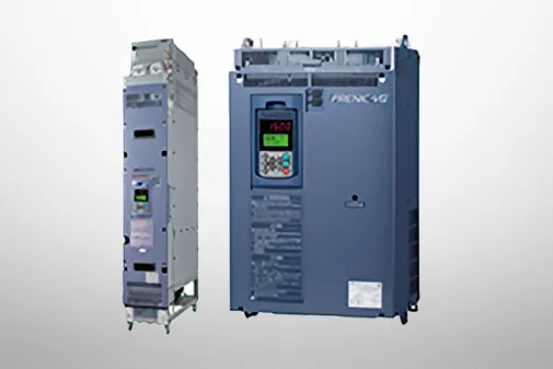
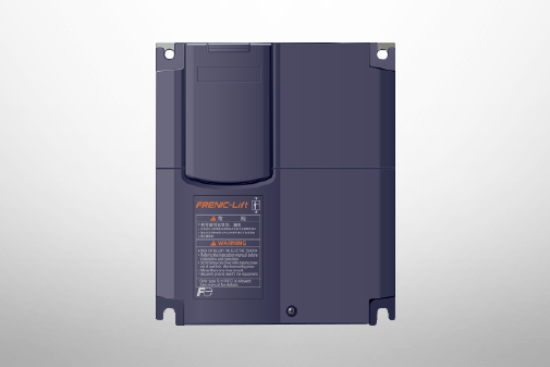
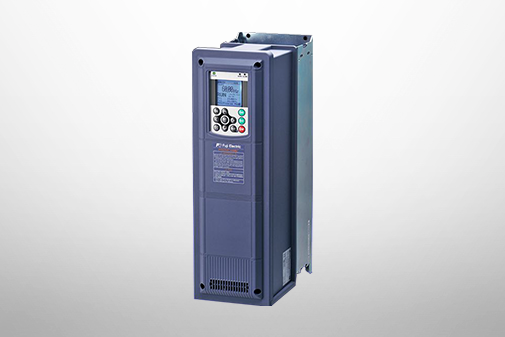
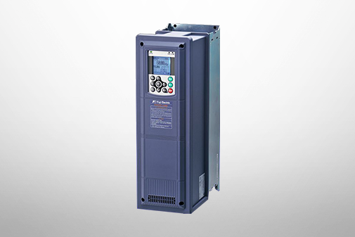
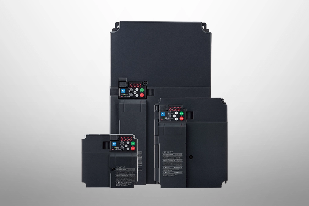
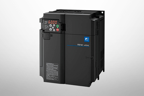
FRENIC-VP (F2)
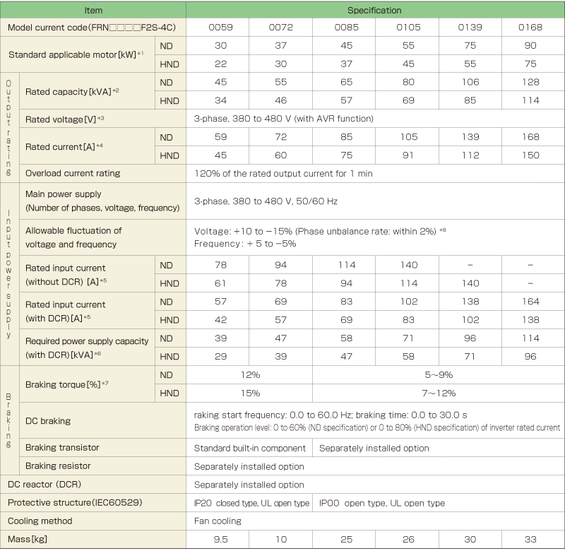
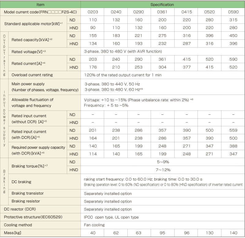
Specifications | Three-phase 400V
This model is not available in your region.
For more information regarding this product, please contact us via the inquiry form.
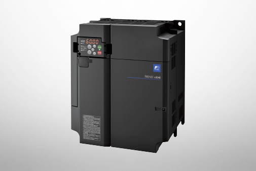
This model is not available in your region.
For more information regarding this product, please contact us via the inquiry form.
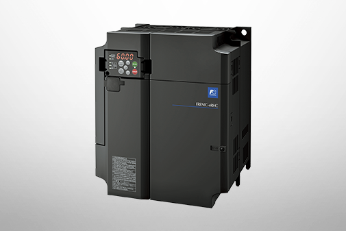
This model is not available in your region.
For more information regarding this product, please contact us via the inquiry form.


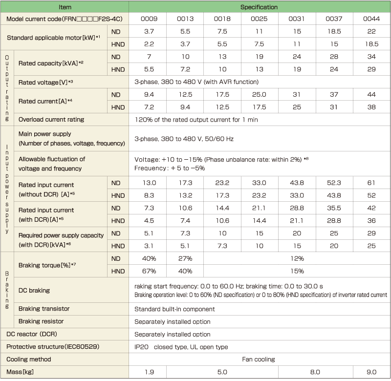
Three-phase 400V (Basic Type)
2.2 to 22kW
22 to 90kW
-
Note1
-
The standard applicable motor shown refers to a Fuji Electric 4-pole standard motor. When selecting this product, make the selection based not only kW but also make sure that the inverter output rated current is greater than or equal to the motor rated current.
-
Note2
-
Rated capacity is calculated using an output rated voltage of 440 V.
-
Note3
-
Voltage exceeding the power supply voltage can not be output.
-
Note4
-
Reduction is necessary when the carrier frequency (function code F26) is set to the following value or higher.
HND: Model code of 0009 or less: 8 kHz; 0013 to 0059: 10 kHz; 0072 to 0168: 6 kHz; 0203 or more: 4 kHz
ND: 4 kHz
For the ND specification, when the ambient temperature is 40°C (104°F) or higher, it is necessary to reduce 2% per 1°C (2% per 1.8°F) relative to the rated current listed in this document.
-
Note5
-
Use a DC reactor (DCR) when the applicable motor is 75 kW or greater.
-
Note6
-
Indicates when a DC reactor (DCR) is used.
-
Note7
-
Indicates the average braking torque for the motor alone. (This value varies with the efficiency of the motor.)
-
Note8
-
Phase unbalance rate [%] = ( maximum voltage [V] − minimum voltage [V] ) ÷ 3-phase average voltage [V] × 67
(Refer to IEC 61800-3.)
Use an optional AC reactor (ACR) when using with a phase unbalance rate of 2 to 3%.
90 to 315kW
-
Note1
-
The standard applicable motor shown refers to a Fuji Electric 4-pole standard motor. When selecting this product, make the selection based not only kW but also make sure that the inverter output rated current is greater than or equal to the motor rated current.
-
Note2
-
Rated capacity is calculated using an output rated voltage of 440 V.
-
Note3
-
Voltage exceeding the power supply voltage can not be output.
-
Note4
-
Reduction is necessary when the carrier frequency (function code F26) is set to the following value or higher.
HND: Model code of 0009 or less: 8 kHz; 0013 to 0059: 10 kHz; 0072 to 0168: 6 kHz; 0203 or more: 4 kHz
ND: 4 kHz
For the ND specification, when the ambient temperature is 40°C (104°F) or higher, it is necessary to reduce 2% per 1°C (2% per 1.8°F) relative to the rated current listed in this document.
-
Note5
-
Indicates the estimated value when the power supply capacity is 500 kVA (10 times the inverter capacity when the inverter capacity exceeds 50 kVA) when connected to the power supply with %X = 5%.
-
Note6
-
Indicates when a DC reactor (DCR) is used.
-
Note7
-
Indicates the average braking torque for the motor alone. (This value varies with the efficiency of the motor.)
-
Note8
-
Phase unbalance rate [%] = ( maximum voltage [V] − minimum voltage [V] ) ÷ 3-phase average voltage [V] × 67
(Refer to IEC 61800-3.)
Use an optional AC reactor (ACR) when using with a phase unbalance rate of 2 to 3%.
-
Note9
-
A power supply voltage switching connector is provided for inverter models with a capacity code of 0203 or higher. Switch as required according to the applied voltage.
This model is not available in your region.
For more information regarding this product, please contact us via the inquiry form.
This model is not available in your region.
For more information regarding this product, please contact us via the inquiry form.
This model is not available in your region.
For more information regarding this product, please contact us via the inquiry form.
AC Drives (Low Voltage) Support

Download documents
Column

Understanding application, benefits, basic structure, case study, types, and Fuji Electric's inverters with this video.
December 27,2021

Understanding the basics: Differences between inverters and converters
January 20,2021

How and what does an inverter take control of? A brief explanation to grasp the basic structure.
January 20,2021

The fundamentals of inverters and their uses.
January 20,2021