Share
Fuji Electric Product Column
Reduce On-site Pressure Loss
Reduce On-site Pressure Loss
Thoroughly understanding the key points and calculation methods for countermeasures
-

What Are The Reasons and Causes of Pressure Loss in Fluids inside The Piping?
-
Changes Depending on The State of Flow! How to Calculate Pressure Loss in Fluid Friction
-
Summary of Pressure Losses Occurring in Various Pipeline Components in A Piping System
-
How to Cut Unnecessary Energy Costs By Reducing Pressure Loss
What Are The Reasons and Causes of Pressure Loss in Fluids inside The Piping?
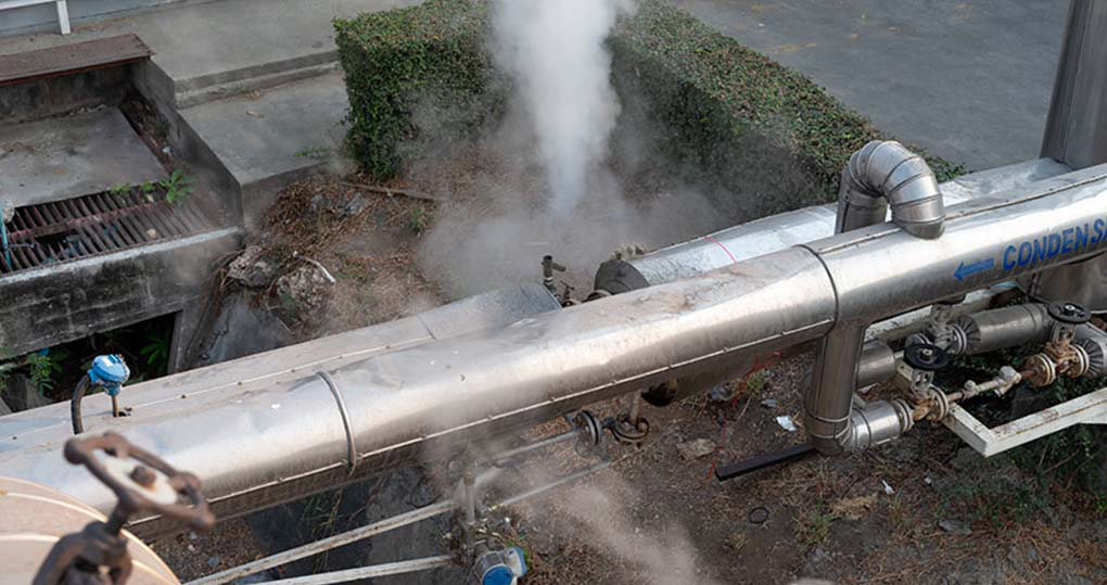
The steam produced in the boiler passes through the piping and is used in the designated factory equipment. At that time, when the steam (fluid) flows through a long pipe, the pressure on the downstream side decreases compared to the pressure on the upstream side. This is the phenomenon called "pressure loss". A decrease in pressure means that the work corresponding to the decrease is lost and, in turn, indicates the same meaning that the energy is lost.
So, what is the cause of "pressure loss" = "energy" loss? Pressure losses are caused by several factors, including the viscosity (stickiness) of the fluid itself, the roughness (friction) of the pipe surface, the fluid's velocity, vortices and disturbances in the flow.
As an analogy, let's imagine yourself as a single particle of fluid (water) and you are walking in a pool. If you try to walk quickly at that time, you will encounter resistance and exhaust yourself. Also, rubbing your body against the pool walls, walking while changing direction along the curves, or adding a sticky oil (a highly viscous fluid) to the pool make it tiring and difficult to walk. Feeling physically tired is a proof that the energy is consumed.
It may be easier to understand it more quickly if you imagine that this kind of effect is also occurring inside the pipes.
Changes Depending on The State of Flow! How to Calculate Pressure Loss in Fluid Friction
Let's try to express the discussion described above by using a few mathematical formulas. To simplify the explanation, let's consider an infinitely long, straight, circular pipe as shown in the figure below.
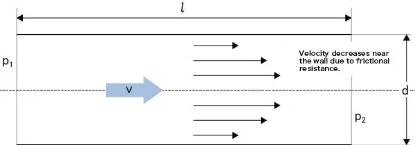
In this case, the basic formula for pressure loss due to fluid friction is as follows:
[Basic formula for pressure loss] (straight pipe)
P1 - P2 = ΔP = λ (l/d) (ρv2/2)
(ΔP: Pressure loss, λ: Pipe friction coefficient, L: Pipe length, d: Pipe diameter, v: Average flow velocity, ρ: Fluid density)
Here, λ (pipe friction coefficient) is a value that changes depending on the irregularities of the pipe's inner wall and the flow conditions, as mentioned in the previous analogy example. Then, what exactly does this state of flow mean?
When ink is continuously dropped into slow-moving water, it flows in straight lines. This state is called "laminar flow". However, as the flow gradually becomes faster, it begins to be turbulent at the rear, creating vortices, and it eventually changes into an even more irregular flow. This is the state called "turbulent flow".
To determine whether the flow is a laminar flow or a turbulent flow, a dimensionless number with no units called the "Reynolds number" (Re) is used. The Reynolds number is a numerical value that represents the state of the flow and is expressed by the following formula:
Re = Vd/ν
(V: Flow velocity, d: Inner diameter of pipe, ν: Kinematic viscosity)
When the flow velocity reaches a certain range (it has a range), the flow transitions from a laminar flow to a turbulent flow. The transitional point (critical Reynolds number) is around a value of 2,000 to 3,000.
Then, λ is expressed by the following formula depending on whether the flow is a laminar flow or a turbulent flow:<・
<Laminar flow> λ = 64 / Re
<Turbulent flow> λ = 0.3164 / Re - 1/4
Now, let's go back to the pressure loss formula mentioned earlier.
ΔP = λ(l/d)(ρv2/2)
Since the pressure loss is affected by the square of the flow velocity v, the flow velocity has a significant effect, but the effect of λ is also added to it. Furthermore, during turbulent flow, since Re has a significant effect and λ increases exponentially, the pressure loss becomes very large as well.
Summary of Pressure Losses Occurring in Various Pipeline Components in A Piping System
Actual piping systems are not limited to straight pipelines. For example, in pipes of which diameters vary depending on the positions in a pipe, such as pipe openings with an oblique angle, pipes of which pipe diameter suddenly increases midway, or conversely pipes of which pipe diameter suddenly decreases, vortices are generated and energy is lost. In addition, significant pressure loss occurs even in a "reducer" that connects pipes of different diameters, and in a curved pipe called "bend (elbow)". In particular, the pressure loss increases when the bend angle is 90 degrees or the bend radius R is small.
-
Note
-
See the "Bend (Elbow)" column in the table of explanations below.
In addition, using other machines such as heat exchangers or common flow meters can block part of the flow, causing a loss of pressure.
For reference, the following table summarizes the pressure losses caused by these various pipeline components. The ζ (zeta) used to calculate pressure loss refers to the loss coefficient, which varies depending on the shape of the pipeline and how it is installed.
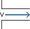
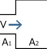
| Pipe inlet 1 Horizontal inlet |
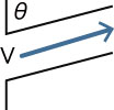
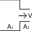
Pipe inlet 2 Inclined inlet |
Sudden expansion pipe A1→A2 (A1<A2) |
Sudden contraction pipe A1→A2 (A1>A2) |
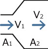
Reducer Area A1/A2 Velocity V1-V2 |
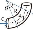
Bend (Elbow) |
  |
  |
 |
  |
  |
  |
| V: Average velocity | V: Average velocity θ: Inclination angle of inlet |
V: Average velocity before sudden expansion A1: Cross-section area before sudden expansion A2: Cross-section area after sudden expansion |
V: Average velocity after sudden contraction A1: Cross-section area before sudden contraction A2: Cross-section area after sudden contraction |
A1: Cross-section area before sudden expansion A2: Cross-section area after sudden expansion V1: Velocity before expansion V2: Velocity after expansion |
R: Center radius d: Inner diameter of pipe θ: Bend angle l: Axial length of circular pipe |
| ζ = 0.5 (with inlet angle) ζ = 0.25 (inlet chamfer) ζ = 0.005 to 0.06 (inlet rounding) |
ζ = ζ0+0.3COSθ + 0.2COS2θ |
ζ = (1-A1/A2) 2 | ζ = (1-A1/A2) 2 | ζ: Expansion by A2/A1 Change by the angle θ |
ζ = (0.131+0.1632 (d/R) 3.5 (θ/90) |
| ΔP = ζρV2/2 (ρ: Fluid density) | ΔP = ζρ(V1-V2)/2 (ρ: Fluid density) |
ΔP = (ζ+λl/d) ρV2/2 (ρ: Fluid density) |
|||
How to Cut Unnecessary Energy Costs By Reducing Pressure Loss
When a pressure loss occurs, the corresponding amount of energy is lost, which results in a decrease in the flow rate and velocity. In that case, the sufficient amount of fluid will not reach the factory equipment and other areas where it should be used. Therefore, it is necessary to operate fluid machineries such as pumps (for liquids) or blowers and compressors (for gases) with sufficient energy to compensate for the pressure loss, which results in wasted energy costs.
Then, in order to reduce the pressure loss to minimum and reduce the energy costs, what kind of countermeasures should be taken?
The key point for actually installing steam piping in a factory is to design the flow path in advance to minimize pressure loss and to select the optimal valves and flow meters.
The easiest solutions that come to mind are to shorten the pipe length or increase the pipe diameter. In order to shorten the length of the pipe, while it may be possible to install a new facility near the boiler room, this solution may not be practical due to the limitations of the factory layout. While increasing the pipe diameter can reduce pressure loss, it will raise the piping cost.
Therefore, in the case of steam, since the balance between the piping cost and the pressure loss will be improved by designing the flow velocity to be about 30 m/s, it seems that the piping is designed using this figure as a guideline. To reduce the pressure loss, it is better to check the entire piping to ensure that there are no unnecessary pipes left. That alone may be surprisingly effective. Also, when the time comes, check the old piping and consider replacing any areas that may cause problems, such as changing such areas to straight pipes.
At that time, it may be necessary to measure the fluid's velocity and flow rate, as well as to examine the condition (quality) of the fluid. In that case, it is convenient to use a flow meter to measure the flow rate of steam, etc. However, when installing a flow meter, if it causes turbulent flow or pressure loss, the product will be of little use.
Therefore, it is also important to select equipment with low pressure loss. These kinds of problems can be solved by selecting an ultrasonic type that can measure fluids without contact and allows to easily change the measurement points.
Recommended
A Thorough Guide to The Causes and Solutions for Steam Leaks
A Thorough Guide to The Causes and Solutions for Steam Leaks
March 13,2026

What Energy-saving Measures Can Be Implemented in Steam Equipment?
What Energy-saving Measures Can Be Implemented in Steam Equipment?
March 6,2026

Why Is Saturated Steam Important in The Industrial Sector?
Why Is Saturated Steam Important in The Industrial Sector?
March 6,2026
Waste Heat Recovery
Waste Heat Recovery
March 6,2026