Servo Systems
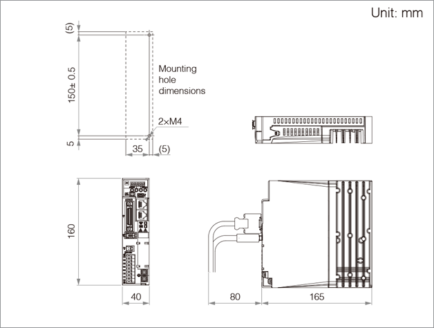
ALPHA7S | Servo Amplifier External Dimensions


-
Servo Amplifier External Dimensions
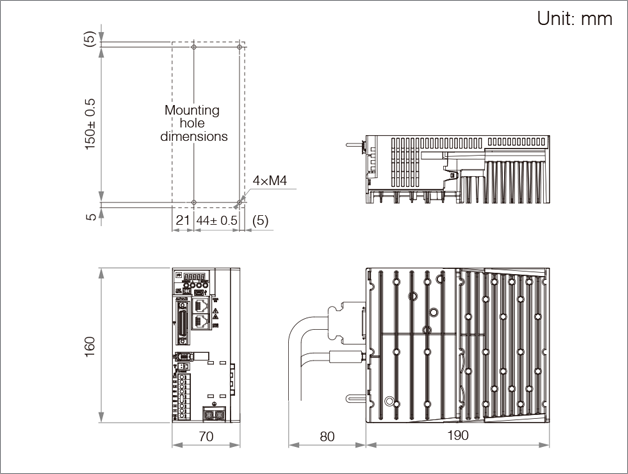
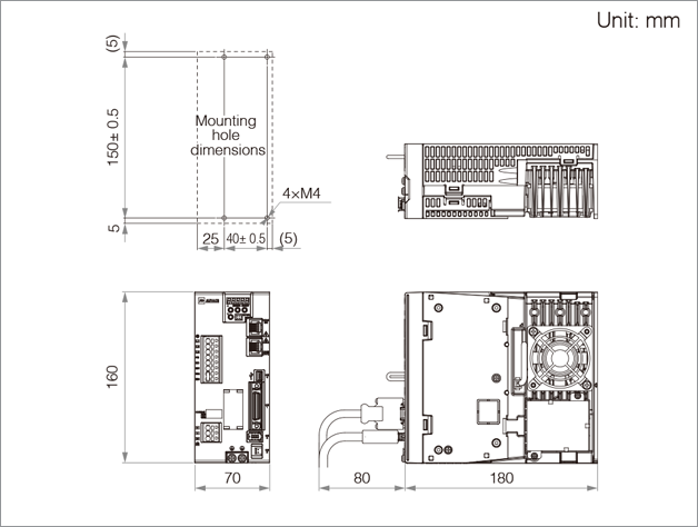
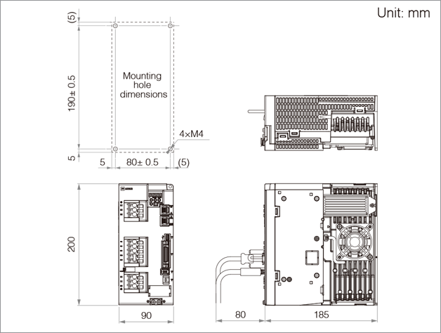
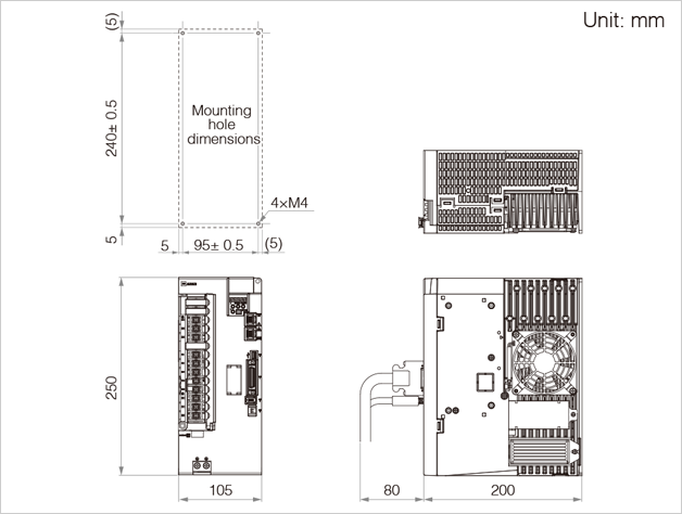
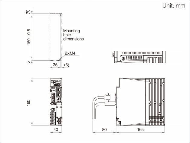
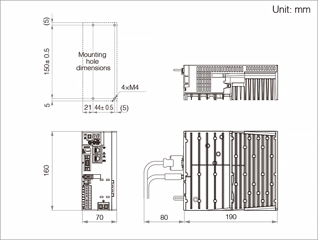
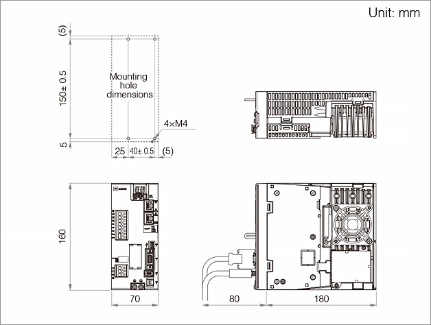
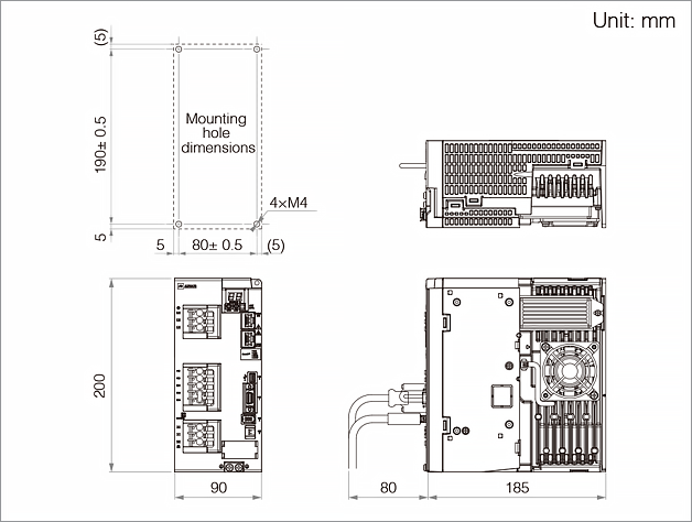
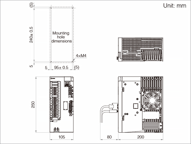
Servo Amplifier External Dimensions
VVS type
Frame 1
Frame 2a
Frame 2b
Frame 3
Frame 4
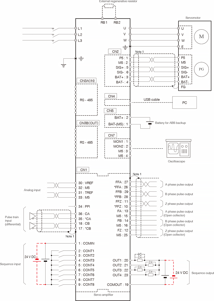
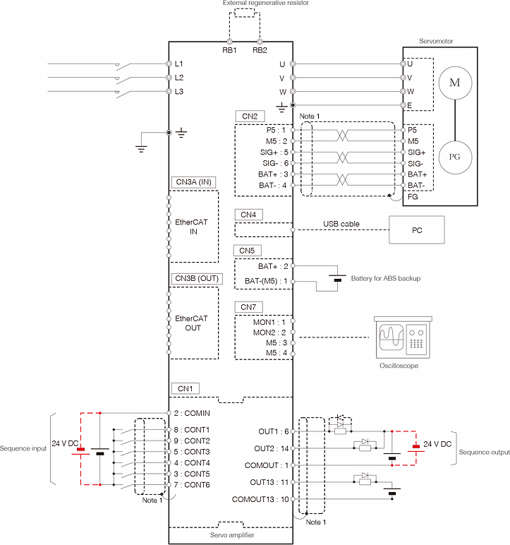
Connection Diagram for Reference(Frame 1)
-
Note 1
-
The shielded wire on the servo amplifier side connects to the connector shell.
-
Note
-
The diagram shown above is intended as a reference for model selection.
When actually using the selected servo system, always make wiring connections according to the connection diagram and instructions described in the user's manual.
VCS type
Frame 1
Frame 2a
Frame 2b
Frame 3
Frame 4
Connection Diagram for Reference(Frame 1)
-
Note 1
-
The shielded wire on the servo amplifier side connects to the connector shell.
-
Note
-
The diagram shown above is intended as a reference for model selection.
When actually using the selected servo system, always make wiring connections according to the connection diagram and instructions described in the user's manual.