Servo Systems
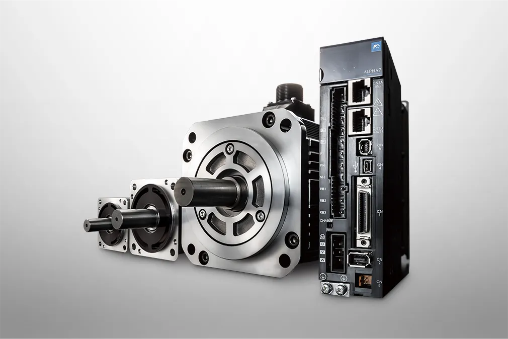
ALPHA7 | Overview


Overview
The Basic Performance at the Highest Level in the Industry
High-speed and high-precision control is realized by the basic performance at the highest level in the industry

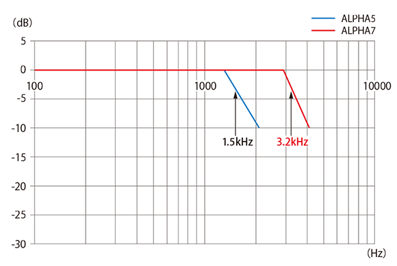
Speed and frequency response at 3.2kHz
Realizes Ultra-High-Speed Control
Fuji's proprietary control algorithm achieves a speed and frequency response at 3.2kHz, the highest level in the industry. This reduces the tact time, enabling high-speed control.

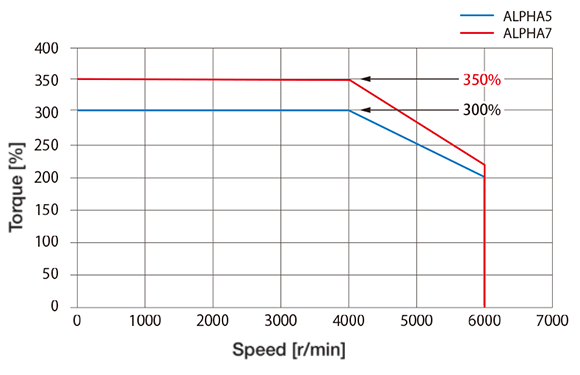
Maximum instantaneous torque of 350%(Note)
Enables Response to High-Speed Commands
The maximum instantaneous torque of the servo motor is now as high as 350%.
-
Note
-
This is applicable only to certain models.

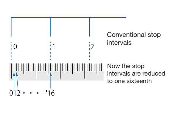
The 24-bit fi ne resolution INC/ABS encoder
Signifi Cantly Improves The Precision of Control
The encoder resolution is now as high as 24 bits.This provides much higher control precision than before, enabling high-precision control.

Safer operations are ensured by
Various Safety Functions
Standard equipment includes the STO function defi ned in the international standard IEC61800-5-2. In addition, the WSU-ST1 option adds support for SS1, SLS, SBC, and SSM. These safety functions can be easily confi gured with parameters.
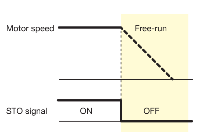
Equipped as Standard with STO (Safe Torque Off)
Upon receiving an input signal from external equipment, the servo system shuts off the output from the servo amplifi er and enters into free-run mode.
*Option
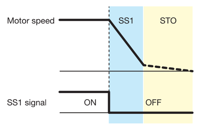
Support for SS1 (Safe Stop 1)
Receiving an input signal from external equipment, the servo system operates the STO function when the speed is reduced to the specifi ed value or the specifi ed period of time elapses.
*Option
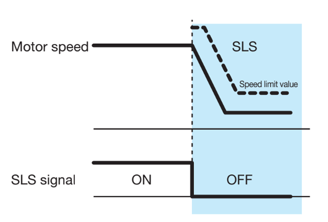
Support for SLS (Safely Limited Speed)
The servo system monitors whether or not the speed limit value is exceeded and, if exceeded, enters into STO mode.
*Option
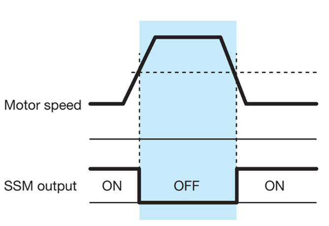
Support for SSM (Safe Speed Monitor)
The servo system outputs the SSM signal when the specifi ed speed is exceeded.
*Option
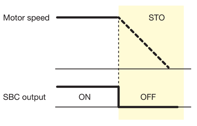
Support for SBC (Safe Brake Control)
The SBC signal is an output signal for controlling an external brake and operates synchronously with STO.
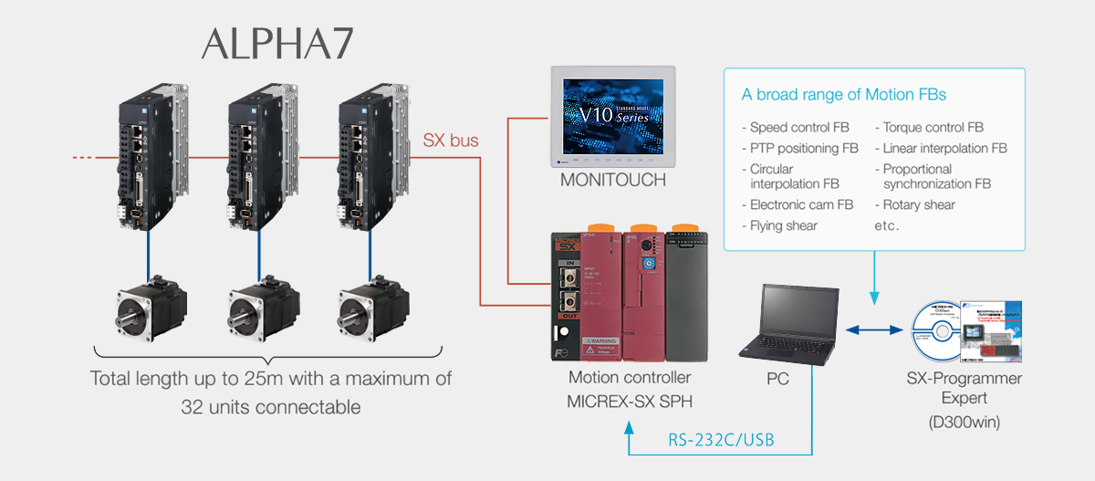
Example System Configuration
High-Speed Serial Bus (Compatible with SX Bus) VS/LS Types
You can easily build a highly functional motion control system that includes synchronous and interpolation control.
Optional Peripheral Equipment and Software
Gain the maximum advantage of ALPHA7 with optional peripheral equipment and software
Motion controller
MICREX-SX
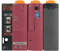
It is possible to perform high-speed processing with a program scan cycle as fast as 0.25ms and I/O refreshing at intervals of 1ms (8192points). You can build a particular motion control system in a short time by choosing from the rich set of FBs (function blocks) and appropriately combining FBs.
Programmable operation display
MONITOUCH V9 series

Supports the VNC server functionality and allows you to remotely monitor and operate MONITOUCH installed at the field from your tablet PC. If an Internet connection environment is available, you can easily implement remote connections in a secure VPN environment.
Version upgrade of SX-Programmer Expert (D300win)
Dedicated Software that Enables Speedy Initial Setup
You no longer have to open one screen for each axis when monitoring the servo operation status. Now you can monitor all the axes from a single screen, thereby being able to configure the operation settings more efficiently.
You no longer have to configure or adjust parameters separately for each axis. Now you can configure or adjust them for up to 32 axes at the same time.
General-Purpose Interface VV Type
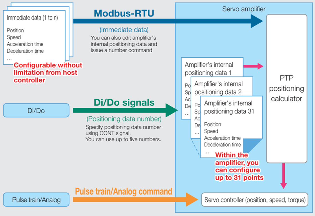
One unit can perform three types of operation.
-
Positioning run (immediate data operation) based on Modbus-RTU
-
Positioning run (with 31positioning data points) based on Di/Do signals
-
Position, speed, and torque control run based on pulse train/analog input
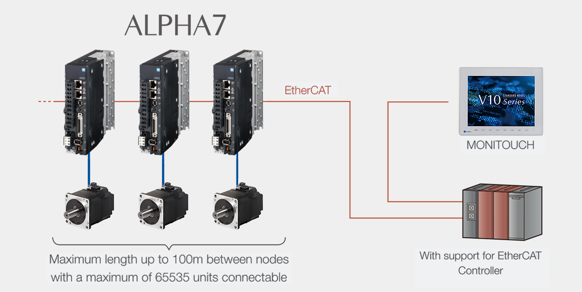
Open Network (with Support for EtherCAT) VC Type
Build and Tune Your System
System construction and tuning is easy and fast, and performance is maximized in combination with MICREX-SX.
Combination with MICREX-SX
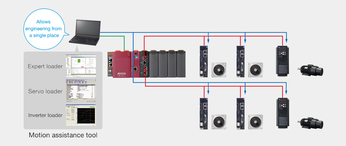
Transparent Communication Allows You to Configure Multiple Amplifiers from a Single Central Location
You can use the transparent communication feature to configure the parameters of multiple Servo Amplifiers from a single PC via the motion controller. In addition, connection with Fuji's MONITOUCH allows Wi-Fi communications with Servo Amplifiers.
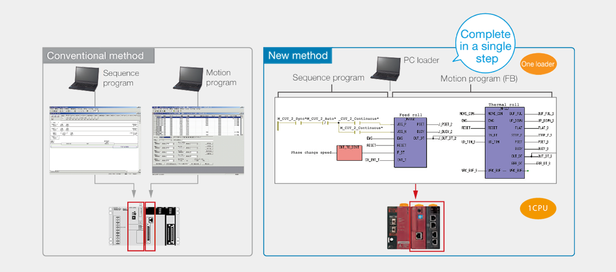
A Single CPU Performs both Sequence and Motion Control
Adding a single unit of MICREXSX eliminates the need of a module dedicated to motion control, thus signifi cantly reducing the initial cost. Also, work effi ciency is dramatically improved by supporting both sequence and motion with a single programming tool(Note).
-
Note
-
SX-Programmer Expert (D300win)
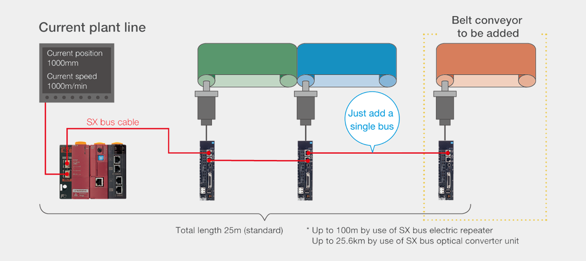
Directly Connectable with a Single SX Bus and Easy to Wire and Extend
Just a single bus cable completes the connection between the controller and servo. When you add an additional control axis to allow for the extension of the machine, you can connect it in a one-touch fashion using a bus cable.
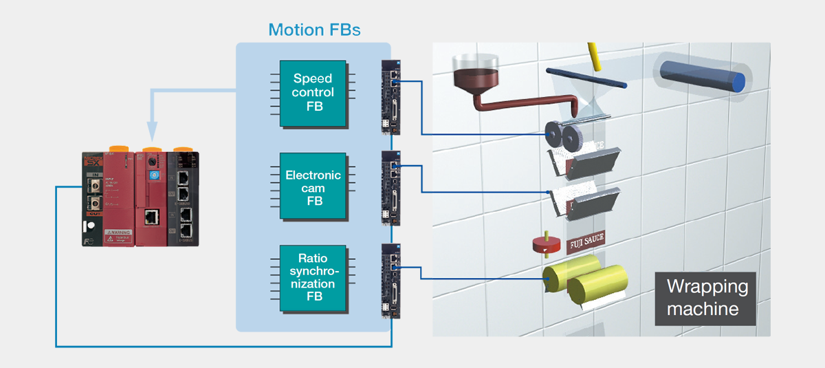
Broad Range of Functional Software "FBs" Raises Development Efficiency
Various software parts, FBs (function blocks), are available free of charge. By appropriately combining FBs, you can build a motion program for a large-scale system in a short time. If you have trouble in developing programs, consult Fuji for support.
Various Features that Allow Standalone Use of ALPHA7
PC Loader Tuning Allows Easy Semi-Automatic Adjustment
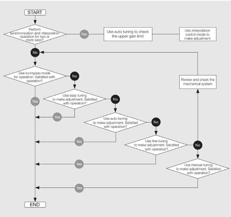
In tuningless mode, you do not have to manually adjust the responsiveness (gain) because the servo system automatically does so. You no longer spend time on tuning at start-up time.
In auto tuning mode, the Servo Amplifier automatically adjust the responsiveness (gain). This mode allows fi ner control than tuningless mode.
This mode is intended for use with machines that require high precision. It allows you to optimize multiple parameters at once, enabling high responsiveness (gain) adjustment.
Features that Reduce the Time Required to Set Up a Newly Introduced Machine
You can adjust the machine and servo before completion of a program for the controller.
You can run a controller program before completion of the machine, so you can debug programs more efficiently.
You can easily perform positioning run, using pre-registered positioning data. You can register positioning data for up to 31points in VV type and up to 99 points in LS type. You can run the system by just selecting a program number and issuing a start command from the host controller. This feature is most useful for the purposes of inching and repetitive operations.
Operation and Stabilization of Quality
Evolved control functions contribute to streamlining ofoperation and stabilization of quality
Evolved Control Functions
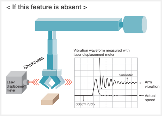
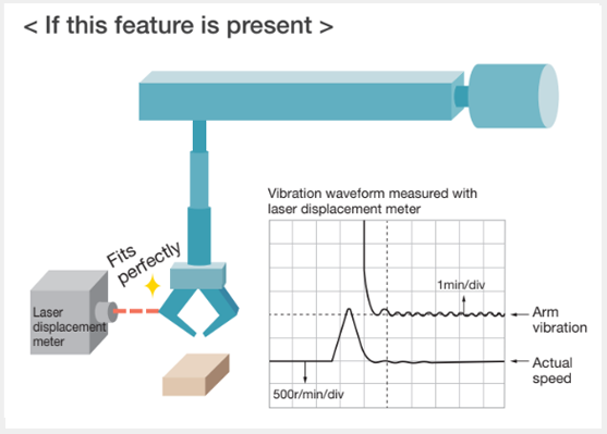
New Damping Control Suppresses the Vibration at Equipment Edges
The introduction of a new control algorithm reduces the vibration at the edges of the equipment to one tenth, compared with the conventional damping control (used in our products). Support for models with three inertia systems makes it possible to control low-frequency vibrations at two points concurrently.
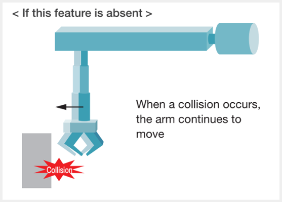
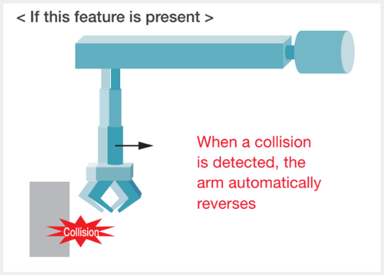
The Interference Detection Feature Detects a Collision, Etc. and Prevents Breakage
The Servo Amplifier detects interference on the equipment (such as a collision with an edge of the machine) and operates to mitigate the shock to the machine when a collision occurs. This feature helps prevent damage to the equipment and reduce load on it.
-
Note
-
Protection may not be complete depending on the operation type.
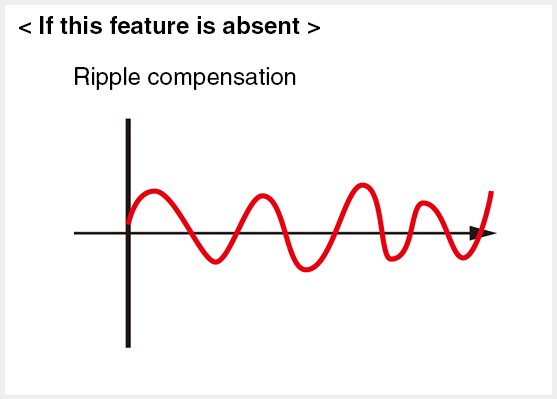
The Cogging Feature Ensures Smooth Operation
Since interference due to cogging of the servomotor is detected and compensated, speed ripples due to cogging can be reduced and smooth operation can be ensured even if the equipment does not support the increase of the speed loop gain.
Maximum Input Pulse Frequency of 4MHz
The system can support input frequencies from the host controller until the maximum frequency of 4MHz is reached.
This allows a fi ner amount of travel per pulse, thus enabling positioning operation at a higher precision than before.
-
Differential input: Max. input frequency ≦ 4.0 [MHz]
-
Open collector input: Max. input frequency ≦ 200 [kHz]
However, the VS type supports only the counter feature and it cannot support pulse train operation.
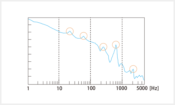
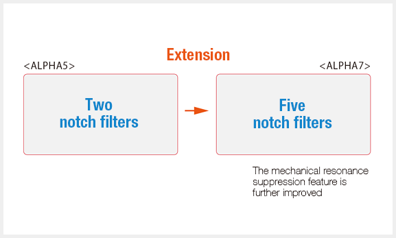
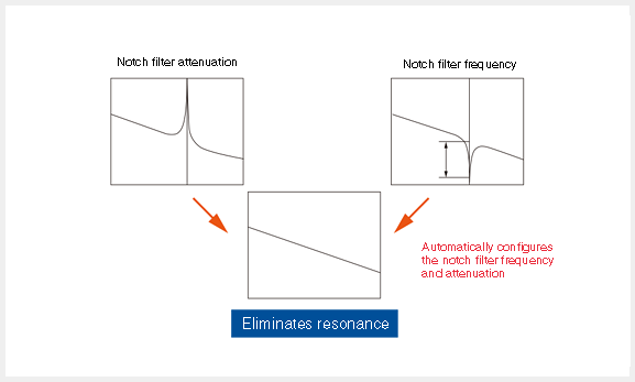
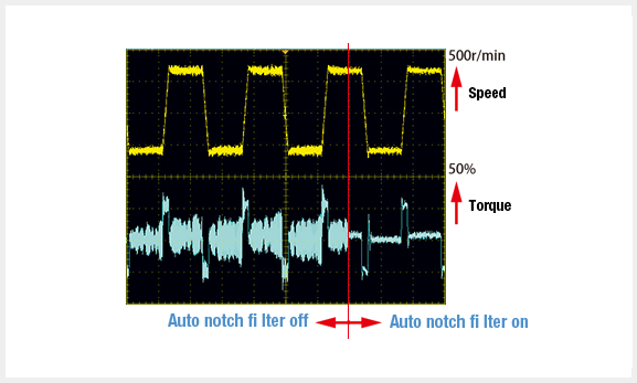
The Notch Filter Feature Suppresses the Resonance of The Machine
Now five notch filters are incorporated instead of two, further improving the machine resonance suppression feature.
The Motor Status Can be Monitored From the Host Controller
The system detects machine resonance and automatically configures the notch filters. While the auto notch filter feature is on, the system constantly performs detection and calculation, thus being able to respond even to moment-to-moment changes in resonant frequency.
One of Three Motor Stop Methods Can be Selected
You can select "rapid deceleration stop", "DB stop", or "coast-to-stop" when an alarm occurs, when the main power is off, or when the servo-on signal is off. Since limiting output torque at desired value is possible even if rapid deceleration stop is selected, impact shock to the machine can be reduced.(Note)
-
Note
-
However, it is enabled when the control power supply is input.
A Homing Program can be Easily Configured
Several homing features allow simple configuration by just combining servo parameters.
(except for EtherCAT type)
Interrupt Positioning Feature
You can easily perform positioning run, using pre-registered positioning data. You can register positioning data for up to 31points in VV type and up to 99 points in LS type. You can run the system by just selecting a program number and issuing a start command from the host controller. This feature is most useful for the purposes of inching and repetitive operations.
(applicable to the VV, VC type only)
Full-Closed Control Function
In addition to the position detection value of the motor encoder, position control can be performed using the position detection value of the external encoder connected to the edge of the machine.
Position control using the position of the edge of the machine allows for more precise control to be achieved.
Design and Features
The design and features reduce the need for maintenance.
Design and Features that Reduce the Labor of Maintenance
Easily Analyze the Cause of Alarm Occurrence
When an alarm occurs, the system displays the content of the alarm as well as related data such as the speed and torque at the time of alarm occurrence. This allows you to accurately analyze the cause of the alarm.
Life Prediction and Preventive Maintenance Features
You can check the status of the servomotor from the controller, so you can perform maintenance at appropriate time. In addition, the system predicts the life for the following consumables and sends the data to the host controller for proactive failure prevention.
-
Battery
-
Main circuit capacitor
-
Cooling fan
Long Life Design of Servo Amplifier Parts
The design life of long-life parts has been further extended:10years for electrolytic capacitors and cooling fans. In addition, the design life of the battery is approximately 35,000hours. (Retention time with the power supply shut off)
-
Note
-
The use conditions are as follows.
-
Ambient temperature: 30°C (annual average)
-
Load factor:Up to 80%
-
Rate of operation:Up to 20 hours/day
The Environmentally Resistant Servomotor can be Used in an Environment with Exposure to Water and Dust
The servomotor is by default compliant with IP67(Note) defined by the International Electrotechnical Commission (IEC). It has Class 6 dust resistance and Class 7water resistance, which means that it can be used in an environment with exposure to water and dust.
-
Note
-
Except for shaft-through part (also except connectors for GYS and GYB motors of lead wire type).
Space-Saving Design
Space-saving design that allows installation in a small space
Space-Saving Design that allows Installation in A Small Space
Most Compact in the Industry(Note) Further Miniaturized Servomotor
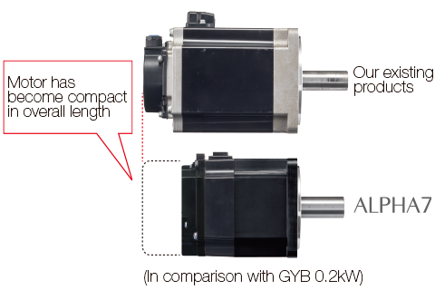
The overall length of the servomotor has been reduced by approximately 15mm, compared with our existing products.
This is the most advanced miniaturization in the industry.
-
Note
-
As of February 2017, for the GYB motor
Compact Servo Amplifier that Can be Mounted in Close Contact
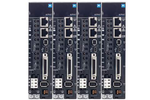
The Servo Amplifier is reduced in width by 5mm and in footprint area by approximately 12%(Note) when compared with our conventional model. It can be mounted in close contact, allowing the reduction of the space required to mount it on the control panel of the machine.
-
Note
-
When mounted in close contact, 80% ED rating applies.There is no restriction when installed at spacings of 5mm or greater.
-
Note
-
Comparison value with frame 1.
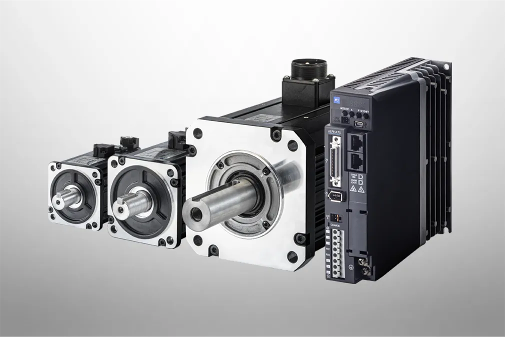
Peripheral Device and Software Compatibility
Compatible with ALPHA5 Motors
ALPHA7 Series Servo Amplifiers can also power ALPHA5 Series motors (GYS5, GYC5, GYG5 (0.75 kW or less)).
For details on ALPHA5 Series motors, refer to “ALPHA5 Catalog 24C-1-E-0037”.
The parameter files used in the ALPHA5 Series can be automatically converted to ALPHA7 Series parameters.The parameter file conversion tool is bundled with the ALPHA7 loader software.
The ALPHA7 loader software is available for free and can be downloaded from the Fe library.
Compliant with Various Standards
Compliance with Overseas Standards and Laws
The ALPHA7 series supports international standards.
<Certification Mark>

-
CE:
-
Compliant with EU (European Union) standards
-
UL:
-
Compliant with the U.S. safety standards
-
cUL:
-
Certifi es the compliance of UL with CSA (Canada safety standards)
-
TUV SUD:
-
An independent certifi cation organization based in Germany
-
TUV Rheinland:
-
An independent certifi cation organization based in Germany
-
KC:
-
Korea's nationally integrated certifi cation mark
By Default Compliant with RoHS(Note 1)

Compliant with RoHS (EU's Restriction of Hazardous Substances) and China RoHS (Management Methods for Controlling Pollution by Electronic Information Products). Environment-friendly design that restricts the use of six hazardous substances(Note 2).
-
Note 1
-
EU's Restriction of Hazardous Substances
-
Note 2
-
Lead, mercury, cadmium, hexavalent chromium, polybrominated biphenyl (PBB),polybrominated diphenyl ether (PBDE)
Harmonic Suppression
All models of Servo Amplifiers used by specific consumers are subject to the "Japanese Guideline for Suppressing Harmonics by Customers Receiving High Voltage or Special High Voltage". All users required to apply guidelines must calculate equivalent capacity as well as harmonic outflow current based on these guidelines, and take appropriate measures if the calculated harmonic current exceeds the limit stipulated for the contracted wattage.
For information on how to calculate the harmonic current, use the following as a reference.
Reference material: Japan Electrical Manufacturers' Association
-
Pamphlet "About Servo Amplifier Harmonic Suppression"
-
JEM-TR225 "Servo Amplifier Harmonic Current Calculation Method for Specific Consumers"
Providing the Best Solutions
We provide the best solution for each customer's usage.
Inspecting instrument used in semi-conductor manufacturing equipment
01 Prober
Solution 1 : To Improve Productivity
-
Fine tuning and feed forward gain
Solution 2 : To Reduce the Vibrations of the Machine
-
Auto damping control and anti-resonant frequency for damping
Used to take out formed products and convey workpieces
02 Takeout Robot
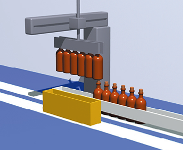
Solution 1 : To Reduce the Vibrations of the Machine
-
Auto damping control and anti-resonant frequency for damping
Solution 2 : To Suppress the Resonance of the Machine
-
Tuningless and notch filter features
Solution 3 : To Prevent Objects from Veing Caught in the Machine
-
Interference detection feature
Used to fill or wrap food or chemical
03 Vertical Wrapping Machine

Solution 1 : To Eliminate Defective Workpieces by Synchronizing the Feed, Seal, and Cut Axes
-
Interpolation operation mode and feed forward control
Solution 2 : To Cut the Material at the Position of the Reference Mark
-
Enable interrupt input
Used to wrap labels around bottles
04 Label Wrapping Machine
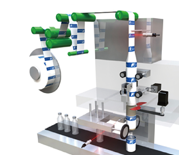
Solution 1 : To Improve Productivity
-
Fine tuning and feed forward gain
Solution 2 : To Establish a Safe System
-
Apply safety functions
Solution 3 : To Cut the Material at the Position of the Reference Mark
-
Enable interrupt input