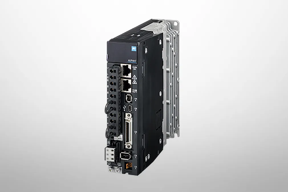
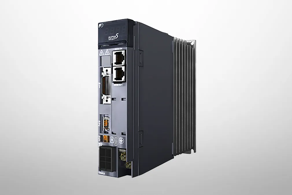
Servo Systems
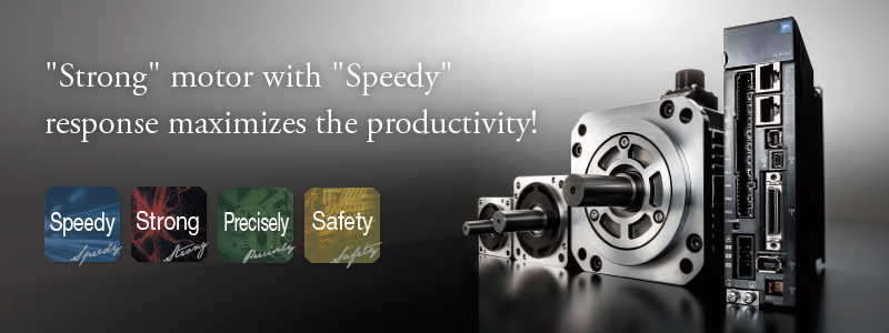
ALPHA7 | Servo amplifier | VS Type
Specification
-
*1
-
The figure is data determined when the amplifier is connected with an external resistor dedicated for each model.
-
*2
-
We will accept custom orders for models without dynamic brake.
-
*3
-
Figure indicates the average of speed fluctuations caused by static load fluctuations, power supply fluctuations, and temperature fluctuations as a percentage of the rated speed.
Outline of System Configuration / Interface specifications
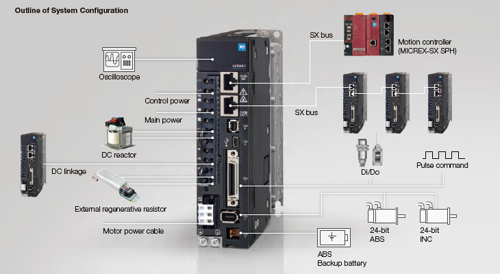
Interface specifications
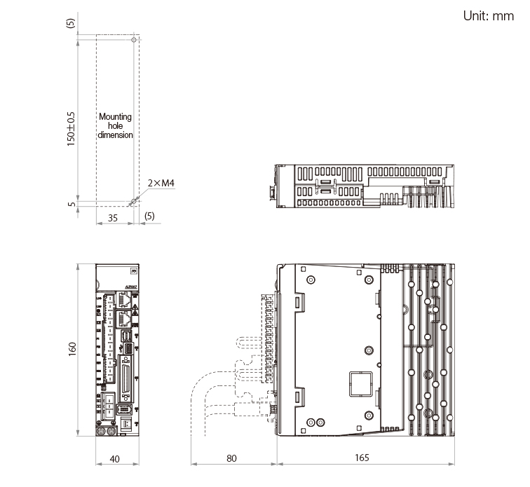
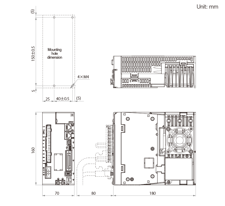
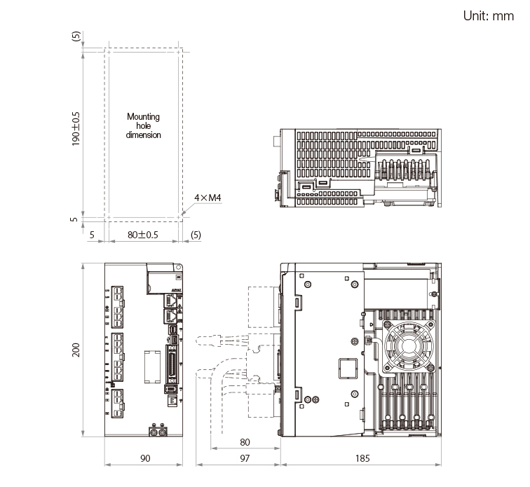
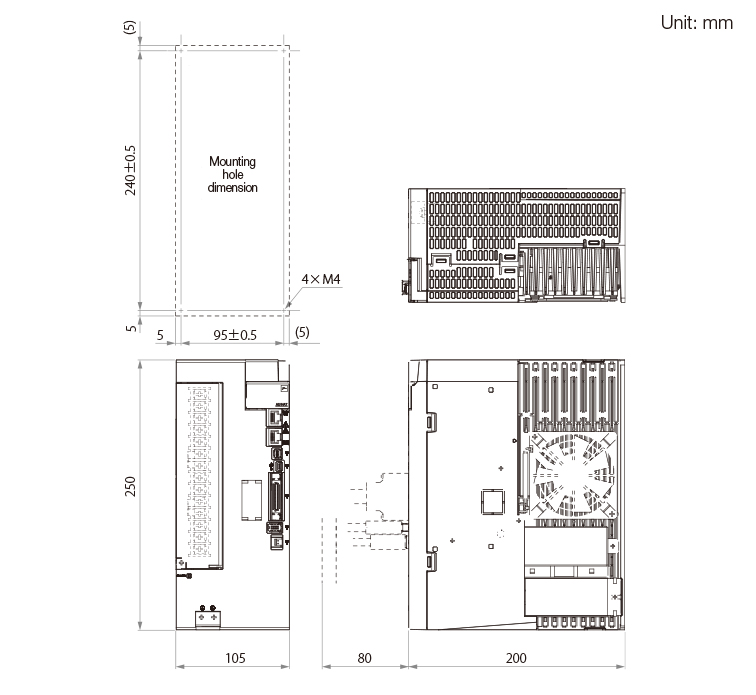
External Dimensions
Frame 1
Frame 2
Frame 3
Frame 4
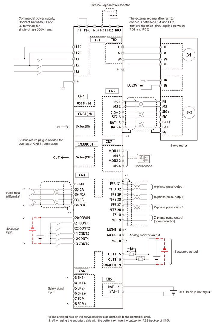
Connection Diagram for Reference(Frame 1)
-
*1
-
The shielded wire on the servo amplifier side connects to the connector shell.
-
*2
-
When using the encoder cable with the battery, remove the battery for ABS backup of CN5.
-
*3
-
To use with the source I/O, connect as shown with the broken line. Connect the surge absorber diode for the output load with polarity reversed.

Caution
The diagram shown above is intended as a reference for model selection.
When actually using the selected servo system, make wiring connections according to the connection diagram and instructions described in the user's manual.
Contact
Please use this form to contact us about prices and delivery dates and to request catalogs.
We accept pre-purchase technical inquiries about products by telephone, fax and email.
Please contact our nearest office about any issues with a product.

