| Output |
Maximum Output Frequency |
5 to 599 Hz, variable setting
(If the output frequency exceeds 599 Hz, the inverter will stop and initiate overspeed protection.) |
|
| Rated Output Frequency |
5 to 599 Hz, variable setting |
|
| Motor Pole Setting |
2 to 128 poles |
|
| Starting Frequency |
0.1 to 60.0 Hz, variable setting
(With speed sensor vector control, 0.0 Hz) |
|
| Carrier Frequency |
FRN****F3S-4C
• 0.75 to 16kHz, variable setting : HND Specifications: **** = 0009 ~ 0059
• 0.75 to 10kHz, variable setting : HND Specifications: **** = 0072
ND Specifications:**** = 0009 ~ 0059
• 0.75 to 6kHz, variable setting : ND Specifications:**** = 0072
Note: To protect the inverter, the carrier frequency may automatically reduce based on ambient temperature and output current conditions (this auto-reduction feature can be disabled). |
|
| Set Resolution |
• Analog Setting: 1/3000 of maximum output frequency |
|
| • Panel Setting: 0.01Hz (below 99.99Hz), 0.1 Hz (100.0 to 599.0Hz) |
|
| • Link Operation: 0.005% or 0.01Hz (fixed) of the maximum output frequency |
|
| Control |
Speed Control Range |
1 : 20 |
VF
SCVF |
| 1 : 200 |
DTV |
| 1 : 10 |
PM-SVC |
| 1 : 2 (Constant torque region: Constant power region) |
VF
SCVF
DTV |
Output Frequency Accuracy
Speed Control Accuracy |
Analog Setting: ±0.2% of maximum output frequency (25 ±10°C) (77 ±18°F) |
VF
SCVF
DTV |
| Panel Setting: ±0.01% of maximum output frequency (-10 to 50°C) (14 to 122°F) |
| Analog Setting: ±0.5% of maximum output frequency (25 ±10°C) (77 ±18°F) |
PM-SVC |
| Panel Setting: ±0.5% of maximum output frequency (-10 to 50°C) (14 to 122°F) |
| Control Mode |
V/f Control |
VF |
| Dynamic Torque Vector Control |
DTV |
| V/f Control with Slip Compensation |
SCVF |
| Encoder-less Vector Control (Synchronous Motor) |
PM-SVC |
Voltage/
Frequency Characteristics |
• Both basic frequency and maximum output frequency can be set between 160 and 500 V. |
|
| • Piecewise V/f Setting (3 points): Any voltage (0 to 500 V) and frequency (0 to 599 Hz) can be set |
|
| • AVR Control can be toggled ON/OFF |
|
| Torque Boost |
• Automatic Torque Boost (for constant torque loads)
• Manual Torque Boost: Any torque boost value can be set (0.0 to 20.0%)
• Selectable Load Types (for constant torque load, quadratic torque decreasing load) |
|
| Starting Torque |
50% or more / 10% speed |
|
| Run, Operation |
• Key Operation:
Run/Stop via [RUN] / [STOP] keys (Standard control panel)
Run/Stop via [FWD] / [REV] / [STOP] keys (Multifunctional control panel: Optional) |
|
• External Signals:
Forward (Reverse) Run, Stop commands [3-wire operation available], (digital input)
Free-run command, external alarms, anomaly reset, etc. |
|
• Link Operation:
Operation via RS-485 communication (Standard built-in), fieldbus communication (Optional) |
|
• Run command switching:
Remote/Local switching, Link switching |
|
| Frequency Setting |
• Key Operation:
Settings via [UP] / [DOWN] keys |
|
• External Potentiometer:
Set via variable resistor (External resistor: 1 to 5 kΩ, 1/2 W) |
|
• Analog Input:
DC 0 to ±10V (DC ±5V) / 0 to ±100% (Terminal [12])
DC 0 to +10V (DC +5V) / 0 to +100% (Terminal [12][C1] (V2 function))
DC 0 to +10V (DC +5V) / -100 to +100% (Terminal [12][C1] (V2 function))
DC 4 to 20mA / 0 to +100% (Terminal [C1] (C1 function))
DC 4 to 20mA / -100 to +100% (Terminal [C1] (C1 function))
DC 0 to 20mA / 0 to +100% (Terminal [C1] (C1 function))
DC 0 to 20mA / -100 to +100% (Terminal [C1] (C1 function))
The [C1 function] and [V2 function] of Terminal [C1] cannot be used simultaneously. |
|
• UP/DOWN Operation
Increase or decrease frequency when the digital input signal is in the ON state |
|
• Multi-stage Frequency Selection:
Up to 16 stages (0 to 15 stages) |
|
• Mode Operation:
Automatically operates according to pre-set run time, rotation direction, acceleration/deceleration time, and set frequency.
Up to 7 levels can be set. |
|
• Link Operation 1:
Set via RS-485 communication or fieldbus communication (Optional) |
|
• Frequency setting switch:
2 types of frequency settings can be switched via external signals (digital input):
Remote/Local switching, link switching |
|
• Frequency Auxiliary Setting:
The terminals [12], [C1] (C1 Function) and [C1] (V2 Function)
can be input respectively as additional input options. |
|
• Ratio operation setting:
The ratio value can be set through the analog input signal (terminals [12], [C1]).
DC 0-10V/0(4)-20mA/0-200% (variable). |
|
Reverse operation:
External commands (via terminals) can enable the following settings:
• External switching of DC 0 to +10V/0-100% to DC+10V to 0V/0-100%
(terminals [12], [C1] V2 Function).
• External switching of DC0 to -10V/0-100% to DC-10V to 0V/0-100%
(terminal [12])
• External switching of DC 4 to 20 mA/0-100% to DC 20 mA to 4 mA/0-100%
(terminal [C1] C1 Function)
• External switching of DC 0 to 20 mA/0-100% to DC 20 mA to 0 mA/0-100%
(terminal [C1] C1 Function) |
|
• Pulse column input (Standard):
Pulse input "PIN" = terminal [X5], rotation direction "SIGN" = inputs other than [X5].
For complementary outputs: max 100 kHz,
For open-collector output: max 30 kHz. |
|
Acceleration/
Deceleration time |
• Setting Range: Adjustable within the range of 0.00 to 6000 s.
• Switching: Four acceleration/deceleration times can be set independently and selected for switching during operation.
• Acceleration/Deceleration modes:
Linear acceleration/deceleration, S-curve acceleration/deceleration (weakened, arbitrary adjustments possible via function codes), curve acceleration/deceleration.
• Deceleration mode (free running): When the operation command is set to OFF, the system halts free running.
• Forced stop deceleration time:
A dedicated deceleration time is used to halt during a forced stop (STOP).
S-curve is disabled during forced stops.
• JOG specific acceleration/deceleration Time:
• Acceleration/deceleration time can be switched to 0 by canceling BPS (Block Pulse Speed) through operation. |
|
Frequency limits
(Upper limit,
Lower limit frequency) |
• Both upper and lower frequencies can be set in Hz.
• When frequency is below the lower limit, select whether to continue operation or stop as per lower frequency.
• Settings can be configured through analog inputs (terminals [12], [C1]). |
|
Frequency/
PID command offset |
Frequency setting and PID command deviation can be independently adjusted.
Frequency setting: (Range: 0 to ±200%)
PID command: (Range: 0 to ±100%) |
|
| Analog Input |
• Gain: Adjustable within the range of 0 to 400%.
• Compensation: Adjustable within the range of -5.0% to +5.0%.
• Filter: Adjustable within the range of 0.00s to 5.00s.
• Polarity selection (±/+). |
|
| Jump frequency |
Action points (6 points) and general jump magnitude (0 to 30 Hz) can be set. |
|
| Timed operation |
The system will stop after running for the time set via the keypad. (Single cycle operation.) |
|
Restart after momentary
power failure |
• Power failure trip: Instantaneous trip upon power failure.
• Power-on trip: Free running during power failure, and trip upon restoration of power.
• Deceleration stop: Decelerates to a stop during power failure, and trips afterward.
• Continuous operation: Utilizes the load inertia energy to maintain operation.
• Frequency starts before momentary power failure: Free running during a power failure, and restart at the frequency of the momentary power failure when power is restored.
• Start at the startup frequency: Free running during power failure, and restart at the startup frequency upon power recovery.
• Frequency start upon power restoration: Free running during power failure, and retrieval of speed to restart after power restoration. |
|
Current limitation
(Hardware current limitation) |
To prevent overcurrent trips caused by large load variations or momentary power failure that cannot be responded to by software current limits, hardware current limits are applied. (This function can be disabled.) |
|
Current limitation
(Software current limitation) |
• Automatic frequency reduction to keep output current below the preset action value. (This function can be turned off.)
• Selectable operation modes (only during constant speed operation, or during both acceleration and constant speed operation). |
|
| Commercial switch operation |
• Commercial switching command for outputting 50/60 Hz ([SW50], [SW60]).
• Built-in commercial switching sequence. |
|
| Slip compensation |
• Motor slip is compensated to maintain motor speed at the reference speed, regardless of load torque.
• Slip compensation responsiveness (time constant) is adjustable. |
|
Torque limitation
Torque current limitation
Power limitation |
Control the output torque or output torque current to ensure that the output torque is equal to or less than the predefined limit value
• This value can be switched between Torque Limit Value 1 and Torque Limit Value 2.
• Torque limit values can be set individually for each of the four quadrants.
• Both torque limit and torque current limit can be selected. |
|
| PID control |
• PID controller for process control or floating roller control
• Forward/reverse operation switch
• PID command: Keypad, analog input (terminals [12], [C1]), multi-stage command (3 stages), RS-485 communication, fieldbus communication (optional).
• Feedback value: Analog input (terminals [12], [C1]).
• Alarm output (absolute value alarm, deviation alarm)
• Low-level stop function (pressurized operation before low-level stop)
• Anti-reset winding function
• Output limiter
• Integral/differential reset/Integral hold function |
|
| External PID Control |
• PID controller for process control/ On/Off controller (1 channel)
• Forward/reverse action switching
• PID command: Keypad, analog input (terminals [12], [C1]), multi-stage command (3 stages), RS-485 communication.
• PID feedback value: Analog input (terminals [12], [C1])
• Alarm output (absolute value alarm, deviation alarm)
• PID feedback anomaly detection
• Sensor input conversion function
• PID output limiter
• Integral reset / hold function
• Anti-integral windup function |
|
| Retry |
After a trip, the inverter automatically resets and can be restarted once the trip is cleared.
(Retries count and waiting time before reset can be set.) |
|
| Run-in |
Before starting, estimate the motor speed, allowing the motor to start without halting its idling operation. (Motor constants must be tuned: offline tuning.) |
|
Regenerative Braking
Avoidance Control |
• During deceleration, if the DC intermediate voltage/torque calculation exceeds the regenerative avoidance value, overvoltage trips are prevented by extending deceleration time automatically.
(Specify whether to enforce deceleration after exceeding three times the deceleration time.)
• During constant speed operation, if the torque calculation exceeds the regenerative avoidance value, overvoltage trips are prevented by controlling frequency increases. |
|
Deceleration Characteristics
(Enhanced Braking Capability) |
• During deceleration, increase motor losses and reduce regenerative energy in the inverter to avoid overvoltage trips.
• It can be configured when AVR is not used in combination. |
|
Automatic
Energy-Saving Operation |
Control output voltage to minimize both motor and inverter losses. |
|
| Overload Avoidance Control |
When overload causes an increase in ambient temperature and IGBT junction temperature, reduce the inverter output frequency to avoid overload. |
|
| Offline Tuning |
• Tune motor constants for both rotating and non-rotating motors. (Induction motors, Permanent magnet synchronous motors)
• Tune mode for induction motor %R1 and %X. |
|
| Online Tuning |
Control motor speed variations caused by increased motor temperature during operation. |
DTV |
Cooling Fan
ON-OFF Control |
• Detect inverter internal temperature; stop cooling fan when the temperature is low.
• External control signal output is available. |
|
Motor Characteristics
Selection |
Equipped with standard motor parameters from Fuji Electric. By setting model and capacity, the system can configure proper motor parameters.
• Fuji standard motor 8-series
• HP typical motors
• Fuji high-efficiency motors (MLK1 series / MUL1 series)
• Fuji synchronous motors (GNB2 series / GNP1 series) |
|
| General DI |
Transmit external digital signal status connected to the general-purpose digital input terminals to the upper-level controller. |
|
| General DO |
Output digital command signals from the upper-level controller to the general-purpose digital output terminals. |
|
| General AO |
Output analog command signals from the upper-level controller to the analog output terminals. |
|
| Speed Control |
Two sets of automatic speed regulator (ASR) parameters can be selected. |
PM-SVC |
| DC Braking |
When the inverter starts and stops, DC current is applied to the motor to generate braking torque. |
|
| Rotation Direction Limitation |
Prevent reverse rotation, and prevent forward rotation. |
|
Prevention of
Motor Condensation |
During motor stop, current automatically flows in to raise the motor temperature, preventing condensation. |
|
| Custom Logic I/F |
By selecting digital/analog input/output signals or connecting digital logic circuits or analog calculation circuits, you can construct a simple relay timing sequence for free calculation. (Up to 260 steps) |
|
| Multi-Pump Control |
Control multiple pumps to improve the electrical control of the water delivery system.
• Inverter-Driven Motor Mounting Method
Maximum control units: 5
Inverter variable-speed driven pump units: 1 (fixed), power frequency driven pump units: up to 4 (fixed), auxiliary pump (line-frequency driven): 1 (fixed)
• Inverter-Driven Motor Cycling Method
Maximum control units: 3
Inverter variable-speed driven pump units (cyclical), power frequency driven pump units: up to 2 (cyclical) (When running 3 pumps in a cycle, a relay output interface card (optional) is required),
Auxiliary pump (power frequency driven): 1 (fixed)
• Communication connection mode
Maximum control units: 4
Inverter variable-speed driven pump units: up to 4 (all can be controlled by inverter variable-speed) (Each pump requires a corresponding inverter configuration) |
|
| Function Code Favorites |
Function codes can be added to the favorites menu for display.
(Object: All function codes) |
|
| Data Initialization |
All function codes can be initialized, with specific codes limited.
(Motor, communication-related, and custom logic codes only, limited to favorites) |
|
| Startup Check Function |
For safety reasons, alarms will be displayed when the you power on, reset the alarm, switch operation modes, confirm the presence of operation commands, or enter operation commands. |
|
| Multi-Function Button |
With the standard keypad (TP-M3), the SHIFT button function can be changed to simulate an X-terminal input function.
You may alter the function of the M/SHIFT button on the optional keypad (TP-E2).
This function is disabled by factory default. |
|
F2 Series Function Code
Data Copy |
With the optional keypad (TP-E2), parameters can be transferred from the previous series (F2 series) to the F3 series for copying. |
|
F2 Series Communication
Compatibility Mode |
The inverter is compatible with the communication mode of the previous series (F2 series). Enabling this function allows direct replacement of the F2 series without requiring modifications on the communication master station side. |
|
| Display |
Monitor |
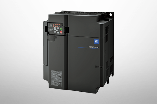
Removable, 7-segment LED (4 digits), 7 buttons (PRG/RESET, FUNC/DATA, UP, DOWN, RUN, STOP, SHIFT),
6 LED indicators (KEYPAD CONTROL, Hz, A, kW, ×10, RUN) |
|
| Running, stopped |
Speed monitoring (set frequency, output frequency, motor speed, load speed, % display speed),
Output current [A], output voltage [V], torque calculation [%], consumed power [kW], PID command value,
PID feedback value, PID output, load percentage [%], motor output [kW], torque current [%], magnetic flux commands [%]
Analog input monitoring, cumulative energy |
|
Inverter Service
Life Forecast |
• Lifetime judgment of main circuit capacitors, electrolytic capacitors on the control board, cooling fans, and IGBT
• Lifetime prediction information can be output externally
• Ambient temperature: 40°C (104°F)
• Load rate: 80% of inverter rated current (HND/ND specifications) |
|
Cumulative
operating status |
• Displays the cumulative operating time of the inverter, cumulative power consumption, motor cumulative operating time/start-up count.
• If the pre-set maintenance time or start-up count is exceeded, forecast information will be output. |
|
| During trip |
Displays the cause of the trip. |
|
| In case of minor fault |
Displays the cause of the minor fault. After the cause is eliminated, it will be recorded in the minor fault history and the display will disappear. |
|
| Fault history |
• Stores and displays the causes of the last 10 trips (codes).
• Stores and displays various operational data during the last 4 trips.
• The date and time will be recorded through the clock function (TP-A2SW). |
|
| PC Loader |
Supported functions |
The engineering PC tool can be used to set and manage inverter parameters and custom logic programs via USB or RS-485 communication. |
|