Share
Fuji Electric Product Column
How does an inverter work?

How does an inverter work?
How and what does an inverter take control of? A brief explanation to grasp the basic structure.
Starting off from the converter circuit and inverter circuit to have a proper understanding of the inverter device
We'll start the introduction by explaining the inverter device's mechanism in detail. The inverter device's role is to control the voltage and frequency of the power supply and seamlessly change the rotation speed of motors used in home appliances and industrial machineries.
The first thing to keep in mind when it comes to enriching your understanding of the internal structure of an inverter device, is that the converter circuit converts alternating current (AC) coming from the power source into direct current (DC), and the inverter circuit changes the converted direct current (DC) back into alternating current (AC). They work as a set. The diagram below shows the role they both play and the way they work.

Firstly, the converter circuit used in the front part constantly converts alternating current to direct current. This process is called rectification. The wave’s direction and magnitude changes periodically over time since alternating current is a sine wave. Therefore a diode, which is a semiconductor device, is used so as to pass electricity in a forward direction to convert it into direct current, but not in the reverse direction.
When direct current goes through the diode, only the forward direction passes electricity and a positive peak appears. However, the other half of the cycle will be wasted because it does not pass the peak in the negative direction. The reason why the diode's structure is shaped like a bridge is so that it can pass the negative peak in a forward direction. This is called full-wave rectification due to the fact that it transforms both the forward and negative wave peaks.
However, full-wave rectification by itself cannot produce a smooth waveform as traces of the alternating current and rippled voltage fluctuations will remain. Therefore, in order to clean these up, the capacitor is repeatedly charged and discharged, gently smoothing and changing the waveform close to that of direct current.
The inverter circuit then outputs alternating current with varying voltage and frequency. The DC/AC conversion mechanism switches power transistors such as "IGBT (Insulated Gate Bipolar Transistor)" and changes the ON/OFF intervals to create pulse waves with different widths. It then combines them into a pseudo sine wave. This is called “Pulse Width Modulation (PWM)”.
The computer controls the pulse width automatically. Some of the dedicated one-chip computers that control the motor include a product with the PWM function pre-installed. This makes it possible to create pseudo sine waves of various frequencies and control the rotation speed of the motor simply by specifying desired parameters.

Categorizing use cases of inverter devices and circuits by voltage and frequency
Inverter circuits and devices are used in various electrical products such as household air conditioners, refrigerators, IH (induction heating) cookers, fluorescent lights, computer power supplies (including UPS), industrial fans, pumps, elevators, and cranes. They are widely used and have become an integral part of our lives.
As mentioned in the beginning, inverter circuits and devices are used in household air conditioners, refrigerators, industrial pumps, elevators, etc. to adjust the motor's rotation speed. In this case, the inverter is used to change both voltage and frequency, this is called "VVVF (Variable Voltage Variable Frequency)".
There are no built-in motors in IH cookers or fluorescent lamps, but changing the frequency with the inverter circuit lets you finely adjust heat and brightness. For example, an IH cooker uses high frequency in its coil that heats the pot, utilizing the inverter circuit. Fluorescent lamps also use alternating current in high frequency to increase the lighting speed in order to maintain brightness and suppress flickering with low power consumption. At this time, the inverter circuit changes only the frequency, so it is called "CVVF (Constant Voltage Variable Frequency)".
Last but not least, the inverter circuit also works in computer power supply units. It may seem meaningless because it is used to output a constant AC voltage or frequency from a constant AC (or DC) voltage or frequency. However, it can be used as a stable power supply when the frequency of the AC commercial power supply fluctuates or a power failure occurs. Since it maintains a constant voltage and constant frequency, it is called "CVCF (Constant Voltage Constant Frequency)".
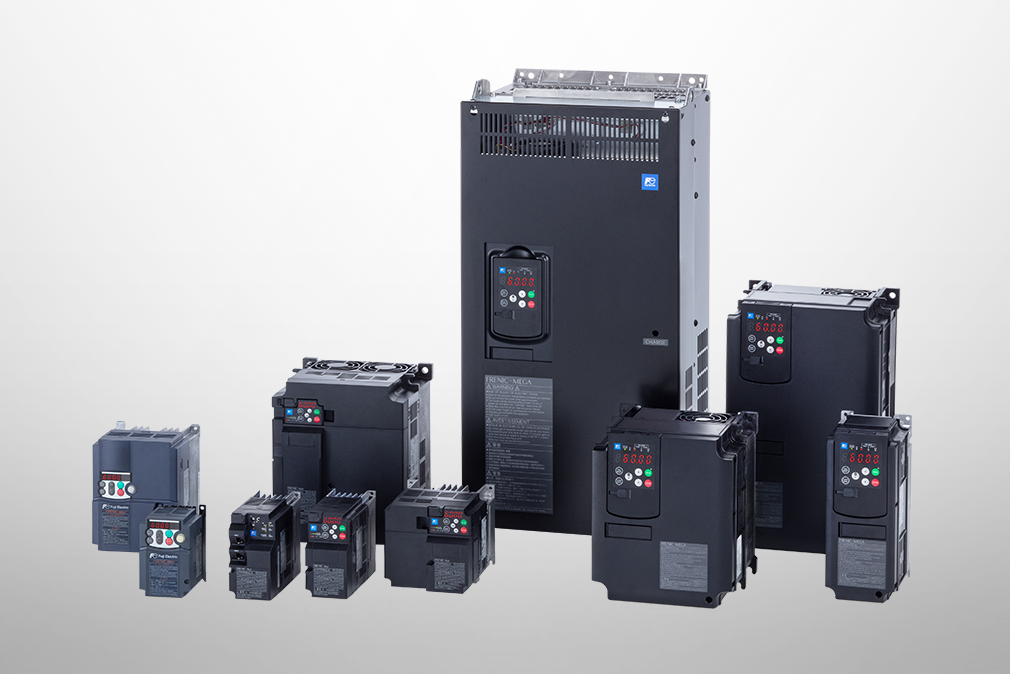
Related products
Recommended

Inverter Basics Video
Understanding application, benefits, basic structure, case study, types, and Fuji Electric's inverters with this video.
December 27,2021

Inverters and converters
Understanding the basics: Differences between inverters and converters
January 20,2021

What Does an Inverter Do ?
The fundamentals of inverters and their uses.
January 20,2021