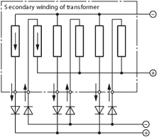
In-phase contra-polarity connection
Some of the difficulties encountered in designing and manufacturing large power conversion equipment are as follows:
(a) Local heating due to large current
(b) Increase of reactance drop at secondary circuit of transformer causing a low-power factor
(c) Current unbalance among different diode/thyristor devices
These have been regarded as inherent problems with large current rectifiers. Fuji Electric's "in-phase contra-polarity connection" system solves these problems.
The features of the system are explained using a simple 3-phase star (Y) connection.
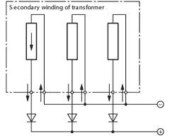
The conventional rectifier circuit using a 3-phase star connection is shown in Fig. 5.
In Fig. 5, the secondary bushings of the transformer are positioned close to each phase, and the star connection is made outside the transformer tank. Only local heating near the secondary bushing is reduced with this construction.
To solve all the problems described above, Fuji Electric designed and patented the "in-phase contra-polarity connection" system.
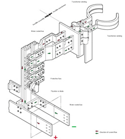
In Fig. 6, the transformer windings of each phase are brought out in parallel to form a path of the rectifier circuit with current flows opposing each other. Fig. 7 shows the physical arrangement of this construction.
Features of the "in-phase contra-polarity connection" construction are as follows.
In case of the construction of Figs. 5 and 6, stray magnetic flux and its heat loss are negligibly small on the surface of the transformer tank where the transformer bushings are brought out.
In Fig. 6, stray magnetic flux and its heat loss are also reduced in the circuit between the transformer and rectifier. As a result, robust carbon steel can be used for the rectifier cubicle enclosure, instead of the non-magnetic material used for the construction of conventional connections.
In Fig. 6, the sectional area of the transformer bushings can be reduced to half that with the conventional connection.
As a result of (1) above, the reactance drop over the circuit between the transformer and rectifier in the rectifier cubicle can be neglected, so that a high-power factor can be obtained.
Current unbalance occurs due to a difference in reactance value in the circuit that connects the diodes/thyristors and transformer.
In the case of the conventional connection shown in Fig. 5, the circuit requires a forced balance reactor to reduce the current unbalance, and complicated analysis must be repeated to determine the value of the forced balance reactor at the design stage.
The construction shown in Fig. 6 requires no such forced balance reactor.