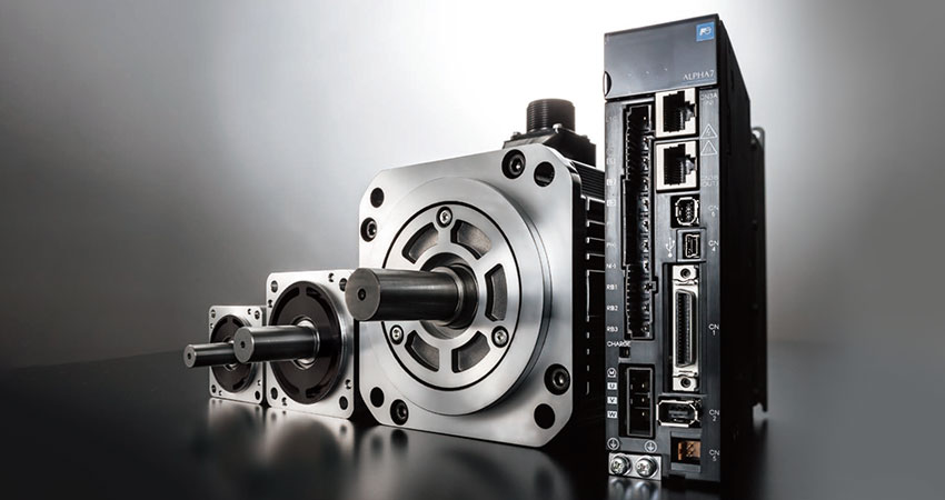
Servo Systems
ALPHA7 | Servo Amplifier External Dimensions


-
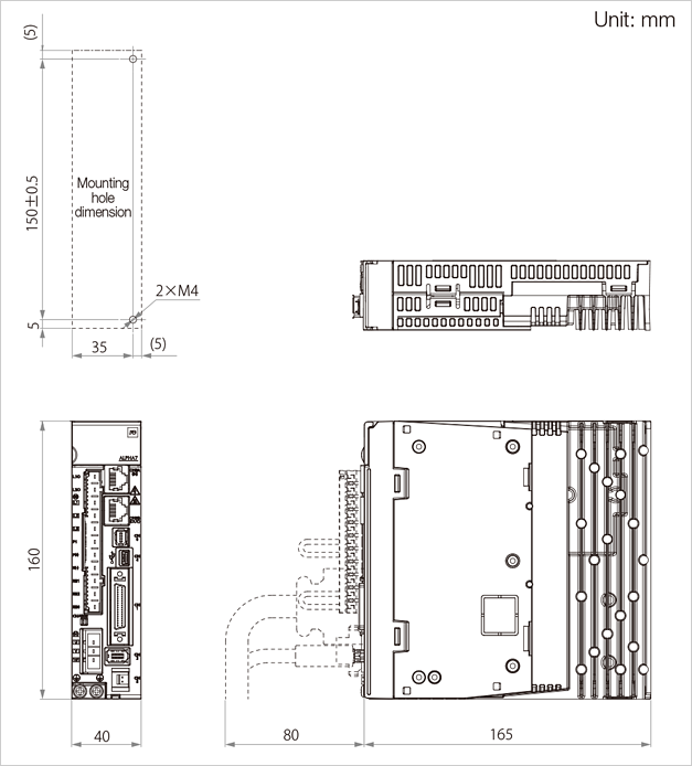
Servo Amplifier External Dimensions
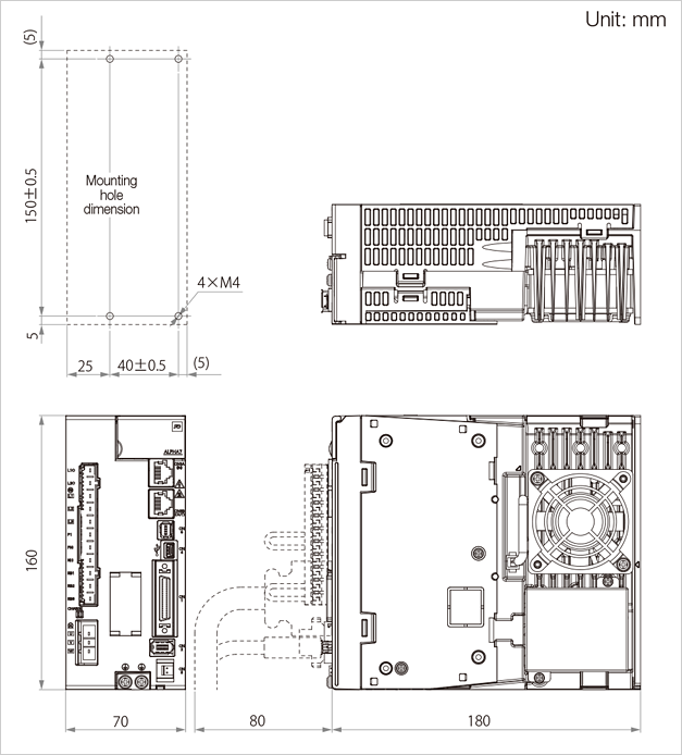
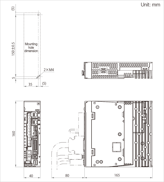
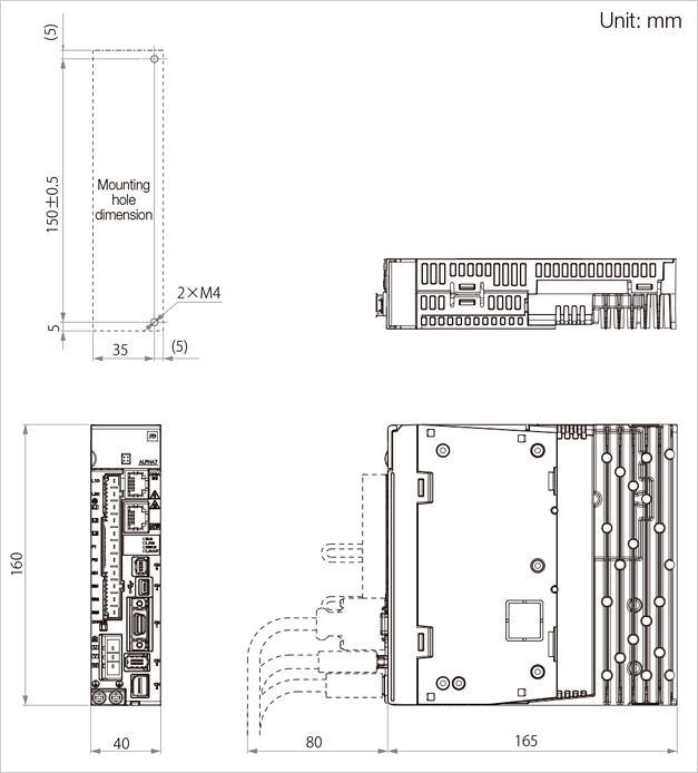
Servo Amplifier External Dimensions
Frame 1
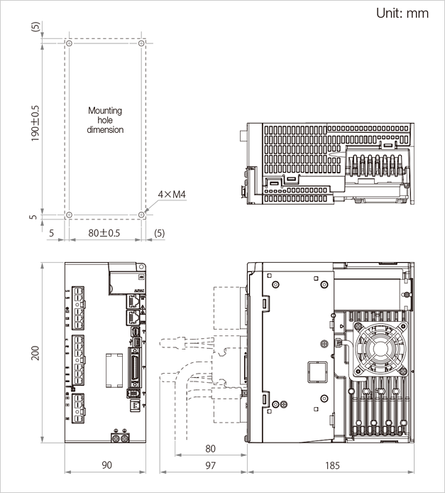
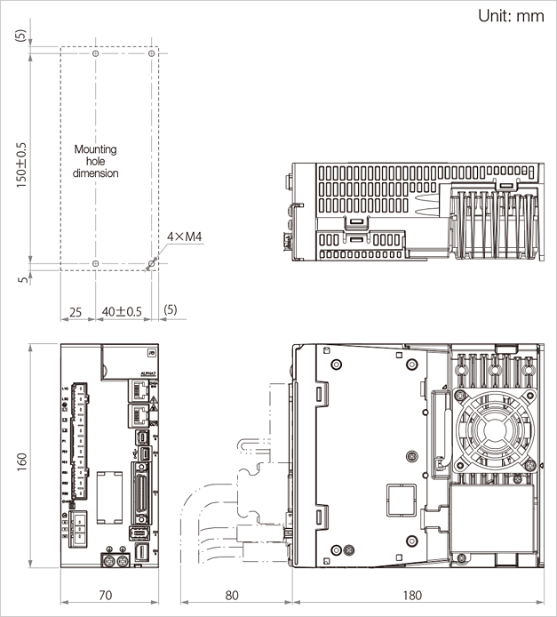
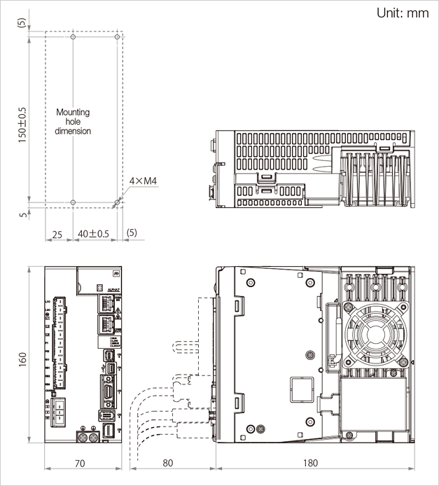
Frame 2
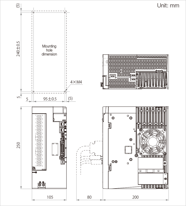
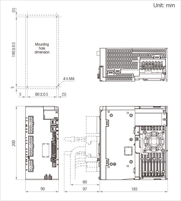
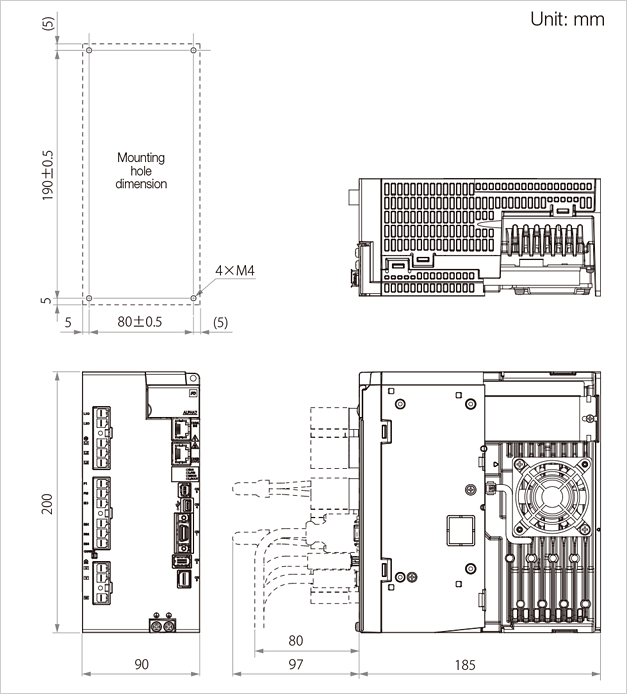
Frame 3
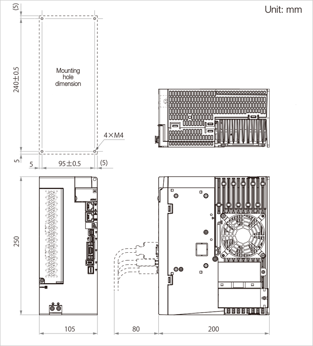
Frame 4
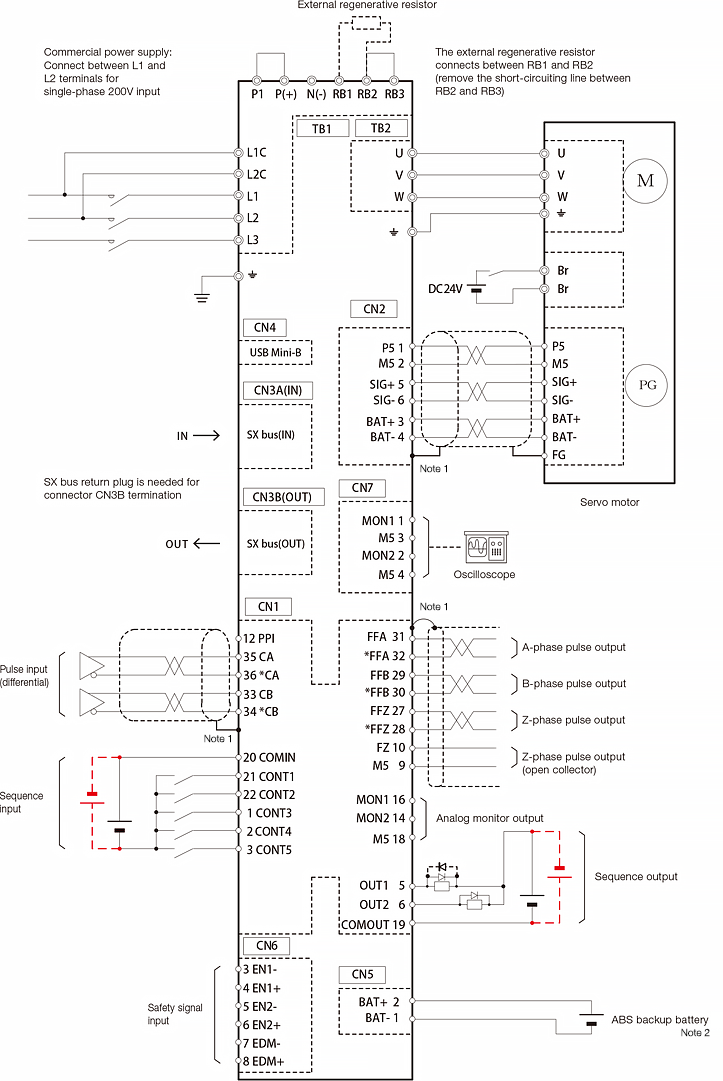
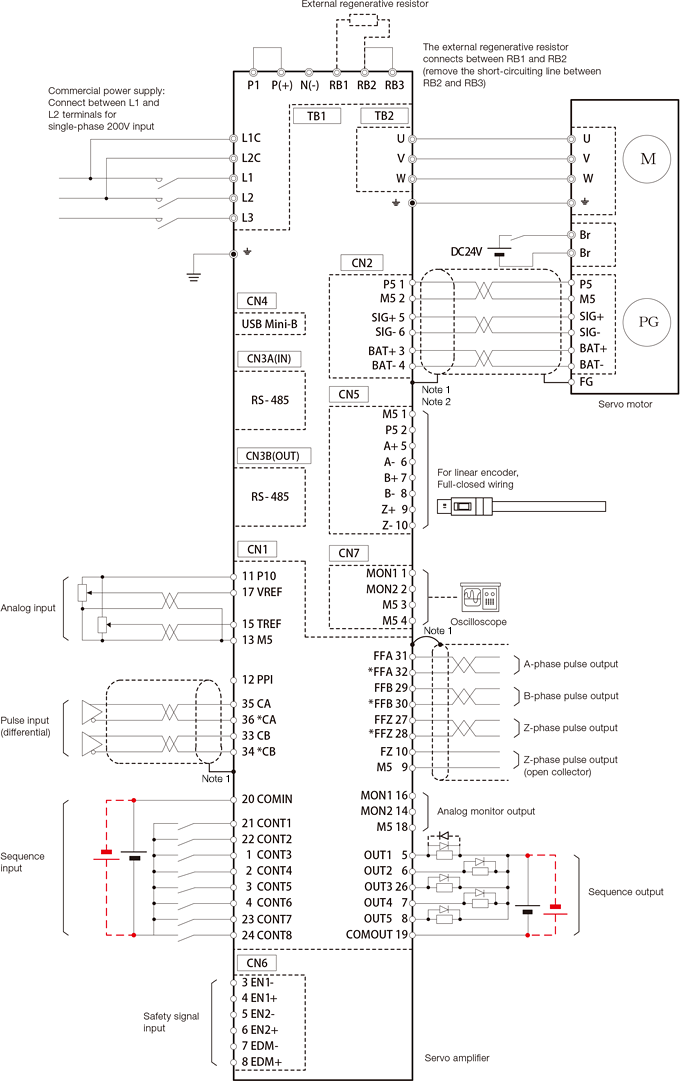
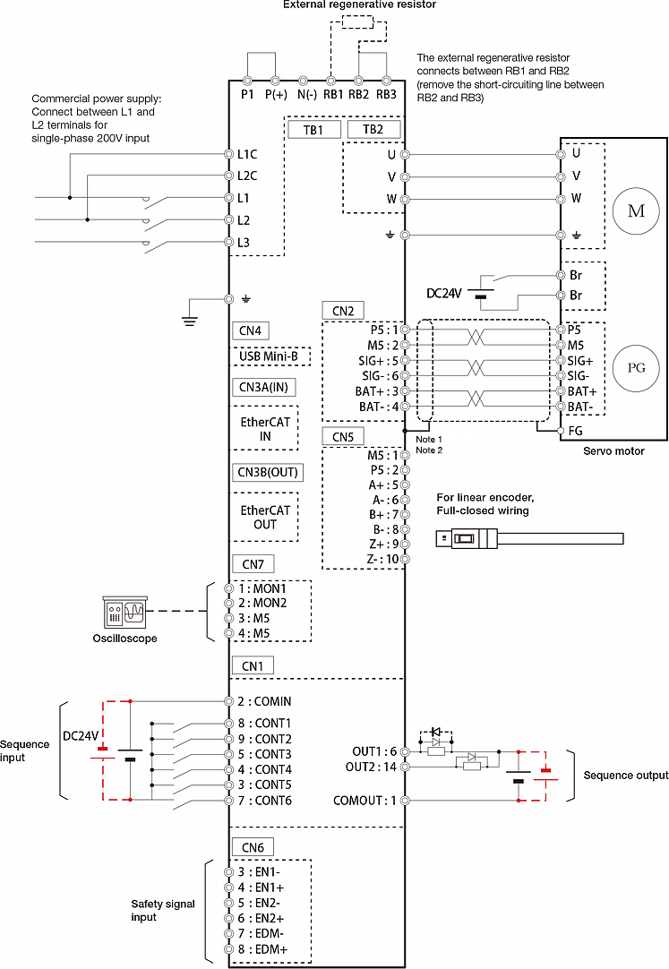
Connection Diagram for Reference(Frame 1)
-
Note 1
-
The shielded wire on the servo amplifi er side connects to the connector shell.
-
Note 2
-
When using the encoder cable with the battery, remove the battery for ABS backup of CN5.
-
Note
-
The diagram shown above is intended as a reference for model selection.
When actually using the selected servo system, make wiring connections according to the connection diagram and instructions described in the user's manual.
Frame 1
Frame 2
Frame 3
Frame 4

Connection Diagram for Reference(Frame 1)
-
Note 1
-
The shielded wire on the servo amplifi er side connects to the connector shell.
-
Note 2
-
To connect an ABS encoder, use an encoder cable with a battery.
-
Note
-
The diagram shown above is intended as a reference for model selection.
When actually using the selected servo system, make wiring connections according to the connection diagram and instructions described in the user's manual.
Frame 1
Frame 2
Frame 3
Frame 4
Connection Diagram for Reference(Frame 1)
-
Note 1
-
The shielded wire on the servo amplifi er side connects to the connector shell.
-
Note 2
-
To connect an ABS encoder, use an encoder cable with a battery.
-
Note
-
The diagram shown above is intended as a reference for model selection.
When actually using the selected servo system, make wiring connections according to the connection diagram and instructions described in the user's manual.