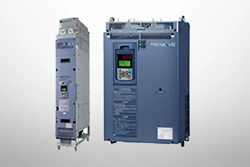
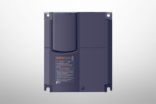
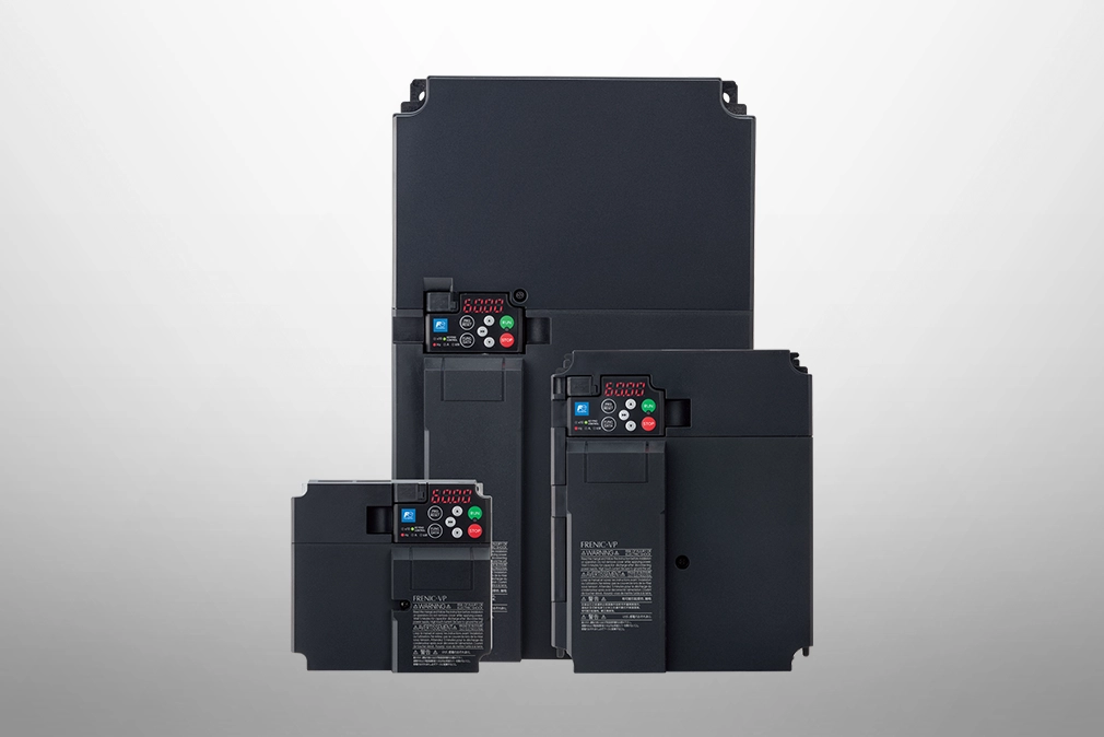
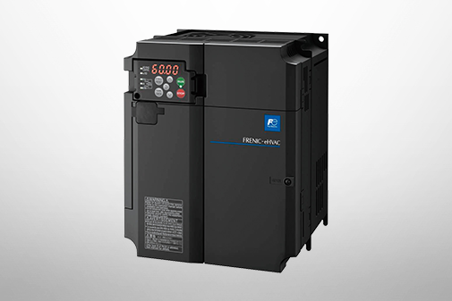
FRENIC-VP(F3)
Product Information


Equipped with a range of applications for controlling fans and pumps.
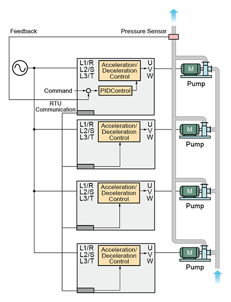
Series Operation
Function to control multiple pumps with one inverter. Control by combining inverter-driven and commercial power-driven operation. The flow and pressure sensor signals are controlled by the PID controller built-in the inverter, and each pump is driven by commercial power or the inverter using switching signals from the inverter.
As a result, when the discharge flow rate is low, only inverter-driven operation is used, and when the discharge flow rate is high, commercial power-driven operation is used in addition to inverter-driven operation to ensure the necessary total discharge flow rate.
FIXED
Inverter-Driven Motor Mounting Method
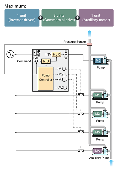
It consists of a combination of a inverter-driven motor (M0), commercial power-driven motors (M1 to M3), and an auxiliary motor (MA).
The inverter-driven motor is fixed to motor M0.
When the desired discharge flow rate is not achieved with only motor M0, control is performed by sequentially adding commercial power-driven motors.
FLOATING
Inverter-driven motor circulation system
![[FLOATING Mode Compatible] High-Efficiency Motor System with Variable Speed and Unit Control](/products/drives_inverters/ac_drives_lv/product_series/__icsFiles/afieldfile/2025/03/24/1204619-img-02_2.webp)
It consists of a combination of motors (M1 to M2) that can switch between inverter-driven and commercial power-driven operation, and an auxiliary motor (MA) that is driven by commercial power. Variable speed control using inverter-driven operation at startup.
If the desired discharge flow rate is not achieved with only the first motor, the operation of FLOATING-1 or FLOATING-2 can be selected.
<FLOATING-1>
・First motor: Switch to commercial drive
・Second motor: Operate using inverter drive
(Each additional motor replaces the inverter-driven motor in sequence)
<FLOATING-2>
・First motor: Continuous inverter drive
・Second motor: Commercial drive
Communication link method :Rotary operation
Each inverter is connected via a communication link, eliminating the need for a controller when building systems.
In addition, the communication link reduces wiring without requiring any additional options.
PID Control (Equipped with 2 PID)
It’s equipped with two loops, one PID loop for motor control and another PID loop for external control.
Both the motor's PID and external actuators can be simultaneously controlled.

Prevention of filter clogging
It detects filter clogging due to dust, etc., based on output current and pressure sensor values, and removes the dust through reverse rotation.
In addition, an alarm is used to indicate that maintenance is required.

Fire Mode
In the event of a fire or other emergency, the inverter's protection function (output cutoff) will not stop, allowing continuous operation to prevent the building from filling with smoke and ensuring clear escape routes.

Continuous Operation Function
In the event of a momentary power failure, the motor speed gradually decreases with the load's inertia, allowing for continued operation and a smooth restart while maintaining motor activity.

Run-in Operation
When you use the inverter to drive a free-running fan, the fan can be smoothly started run-in operation, regardless of the original rotation direction.

By optimizing the control of flow rates, airflow, pressure, and temperature of fan and pump, it makes a significant contribution to energy savings.
Constant control of temperature and pressure differences
Reduces wasteful power consumption by lowering fan output when it is difficult to lower internal temperatures due to environmental factors such as the outdoor air temperature being higher than that of the cooling water.
Temperature can be detected directly with the resistance temperature sensor by using an OPC-PT option card.
-
Note:
-
Thermistor must be prepared separately.

Automatic Energy-Saving Operation Function
Designed for the efficient operation of fan and pump induction motors.
Example of Energy-Saving Characteristics
-
Note
-
The effectiveness varies depending on the motor characteristics.
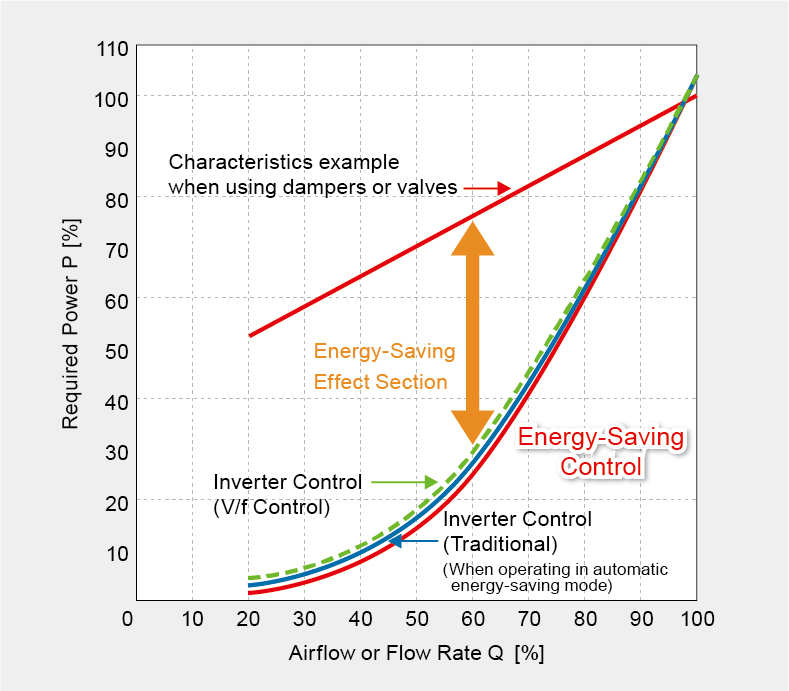
1. Higher efficiency at rated output
2. Efficiency decreases at lower output frequencies (lower load)
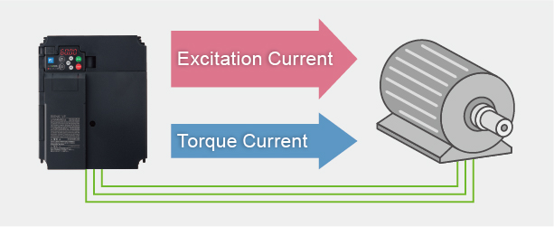
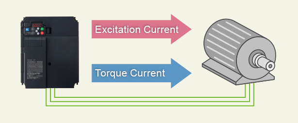
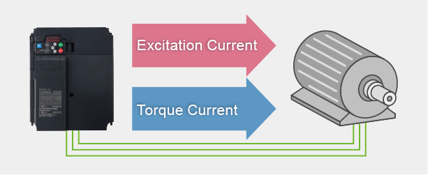
3. Based on load conditions, the motor (excitation current and torque current) and inverter operate at an optimal position to achieve energy savings
Linearize
By measuring the pressure and flow information from the water supply source and feeding it back to the inverter, the system controls the motor speed. By maintaining the terminal pressure at an optimal level, the system reduces power consumption and enhances energy-saving performance.

Wiring and setup are simple, resulting in improved operational efficiency.
Additionally, it is equipped with safety functions, including preventive and predictive maintenance features.
Same mounting dimensions
The installation dimensions of the inverter body are fully compatible.
-
Note:
-
The product can be replaced or installed in place of the traditional F2 series.

-
Note
-
The depth dimension (D) is larger than that of the F2 series; please refer to the dimensional diagram for details.
Simple Wiring
The control terminal block adopts a quick-connect design, significantly improving wiring efficiency.

Easy Parameter Migration
Equipped with a compatibility mode, it allows direct writing of parameters read from the old model.

Enhanced PC loader functions
The product is equipped with a standard USB port (Mini-B), enabling direct communication between the inverter and a computer. Inverter Parameters can be read and written using only the bus power.

Enhancement of alarm history/traceback function
Able to save and display the last 10 alarm histories.
·The most recent 4 entries include detailed data such as output frequency and output current at the time of the alarm.
·The subsequent 6 entries display only the alarm code and occurrence date/time.
-
Note: The date and time data will only be recorded when the TP-A2SW is used and the clock is set.
-
Number of Saved Items
-
Note
-
The above numbers refer to the quantity of waveform files saved.
Life expectancy diagnosis and maintenance functions
The keypad and PC loader make it easy to check the status of equipment and detect problems before they occur, helping to reduce production equipment maintenance time and downtime.

Long life expectancy (main components)
Various lifetime-critical components inside the inverter have been designed with consideration for the maintenance cycles of the customer’s equipment.


-
Note1
-
The above values represent the design lifetime (calculated), not a guaranteed lifetime.
-
Note2
-
The lifetime for ND specifications is 7 years.
Other Safety and Environmental Measures
Revised European RoHS Directive

10 Environmental Load Substances
Lead, Mercury, Cadmium, Hexavalent Chromium
Polybrominated Biphenyls (PBB)
Polybrominated Diphenyl Ethers (PBDE)
Di(2-ethylhexyl) Phthalate (DEHP)
Benzyl butyl phthalate (BBP)
Dibutyl phthalate (DBP)
Diisobutyl phthalate (DIBP)
European RoHS Directive
In view of human health and the environment, and assist in the recycling and disposal of waste electrical and electronic equipment, this directive prohibits the sale of products containing specific hazardous substances.
Chinese RoHS Directive

6 Environmental Load Substances
Lead, Mercury, Cadmium, Hexavalent Chromium
Polybrominated Biphenyls (PBB)
Polybrominated Diphenyl Ethers (PBDE)
Chinese RoHS Directive
The Administrative Measures on the Control of Pollution caused by Electronic Information Products (hereinafter referred to as the "Measures") came into effect on March 1, 2007. The aim is to disclose information regarding the toxic and hazardous substances contained in electronic information products manufactured, sold, or imported into China.
Overseas Application
Complies with overseas safety standards.
  Europe/United Kingdom |
  North America/Canada |
|---|---|
EC Directive
 Low Voltage Directive IEC 61800-5-1 Overvoltage Category III EMC Directive EN 61800-3 ・Emissions: EMC filter options: Category C2 ・Immunity : Second environment |
UL Standards/cUL Standards
 UL61800-5-1 Overvoltage Category III |
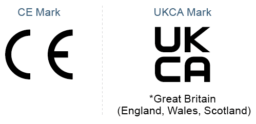
EC Directive:
European harmonized standards issued by CEN/CENELEC/ESTI.
The CE mark indicates that the product meets the necessary safety requirements stipulated by the "EU(EC) Directive". The EMC Directive concerns electromagnetic environmental compatibility, and the Low Voltage Directive governs the electrical safety of equipment operating at AC50–1000 V and DC75–1500 V.
UKCA:
The UKCA mark is for products sold in the UK.
UL Standards/cUL Standards:
UL standards/cUL standards are product safety certification standards established by Underwriters Laboratories Inc. (USA).
UL standards apply in the USA, while cUL standards apply in Canada.
AC Drives (Low Voltage) Support

Download documents
Column
Understanding application, benefits, basic structure, case study, types, and Fuji Electric's inverters with this video.
December 27,2021

Understanding the basics: Differences between inverters and converters
January 20,2021

How and what does an inverter take control of? A brief explanation to grasp the basic structure.
January 20,2021
The fundamentals of inverters and their uses.
January 20,2021