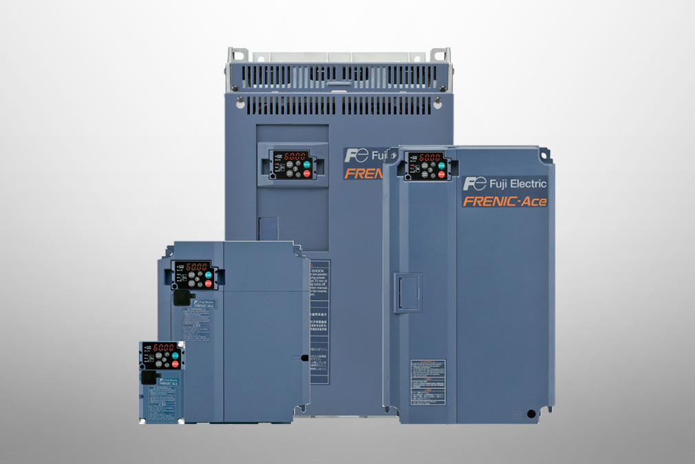
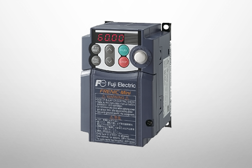
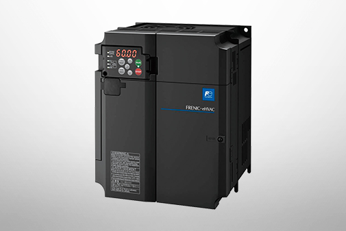
FRENIC-Ace (E3)
Product Information


Provides a full range of motor control and enhanced functionality.
Supports a wide variety of networks to realize IoT.
Faster Operating Speeds
Increases the maximum output frequency of all control systems to 599 Hz and supports applications that require high-speed rotation and minimal speed and torque fluctuations.

Example:Machine tools, compressors, etc.
-
Note
-
Due to revised export control regulations (for frequency converters), the inverter will trip when the output frequency exceeds the upper limit of 599 Hz.
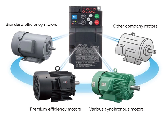
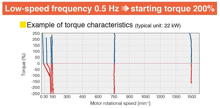
Compatible with Any Motor
Improves speed control range to stabilize torque at low speeds. Enables multi-drive with our induction and synchronous motors, as well as other company motors.
| Induction motor | V/f control | Minimum speed | 1:20 | Base speed |
| Constant torque region | 1:2 | Constant output region | ||
| During sensor-equipped V/f control (Note) | Minimum speed | 1:20 | Base speed | |
| Constant torque region | 1:2 | Constant output region | ||
| Dynamic torque vector control | Minimum speed | 1:200 | Base speed | |
| Constant torque region | 1:2 | Constant output region | ||
| During sensor-equipped Dynamic torque vector control (Note) | Minimum speed | 1:200 | Base speed | |
| Constant torque region | 1:2 | Constant output region | ||
| During sensorless vector control |
Minimum speed | 1:200 | Base speed | |
| Constant torque region | 1:2 | Constant output region | ||
| During sensor-equipped vector control (Note) | Minimum speed | 1:1500 | Base speed | |
| Constant torque region | 1:2 | Constant output region | ||
| Synchronous motors |
During sensorless vector control | Minimum speed | 1:10 | Base speed |
| During sensor-equipped vector control |
Minimum speed | 1:1500 | Base speed |
-
Note
-
Sensor-equipped control needs to install the PG option card.
Advanced Dynamic Torque Vector Control
Enhances our proprietary dynamic torque vector control with new motor constant tuning (that takes into account the voltage of the main circuit) and newly designed magnetic flux observer.
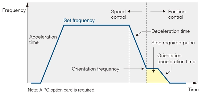
Orientation Function
Capable of rotator positioning, enabling machinery to be held in place via servo locking after stoppage.
-
Note
-
A PG option card is required.
Customizable Logic Functions
Customizable inverter functions to meet your own specific needs. Requires no PLC or external control equipment (relays, timers, etc.) circuits, and can be configured simply by setting and combining various parameters inside the inverter.
| Item | FRENIC-Ace |
| Logic symbol type (Logical operations, counters, timers, arithmetic operations, comparators, limiters, selectors, holders, etc.) |
Total of 138 digital & analog types |
| Number of programming steps | 260 steps |
-
Note
-
Programming available with FRENIC-Loader4.
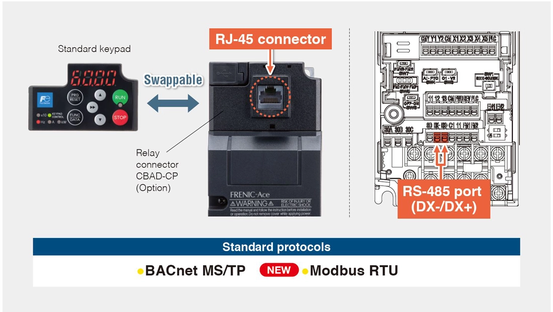
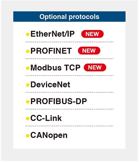
Enhanced Network Functions
Expands supported networks, contributing to reduced equipment wiring and data linkage.
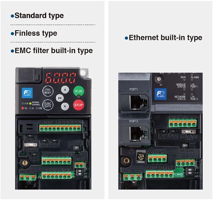
Standard
RS-485 port (DX-/DX+) provided separately from the main unit port (RJ-45 connector). Supports two protocols (Modbus RTU and BACnet MS/TP) using these connections.
Option
Option cards are available to connect to various internationally-popular industrial protocols.
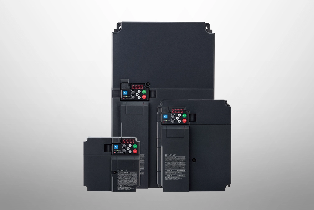
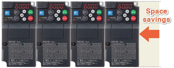
Side-by-Side Installation
Enables side-by-side installation and use at full capacity when multiple inverters are arranged in a panel. Saves space via compact control panel design.
E.g., 3-phase 200 V series 0.75 kW
-
Note
-
Equivalent to conventional E2 Series.
-
Note
-
Install them so that vibration, impact, installation tolerance are taken into consideration. Please note that side-by-side installation can cause problems in removing the adapter for the keypad option.
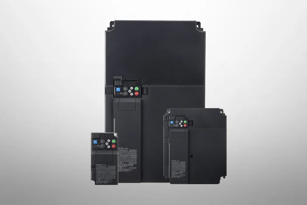
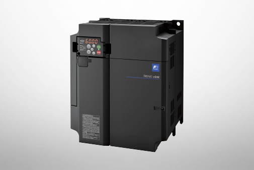
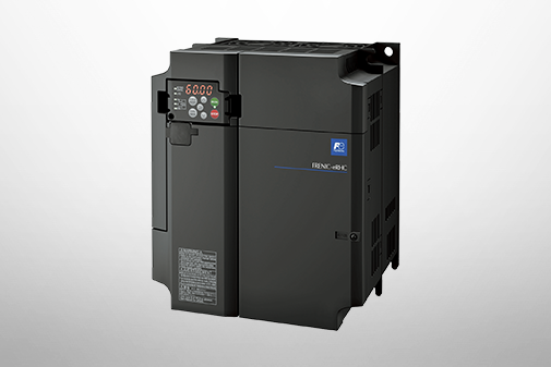
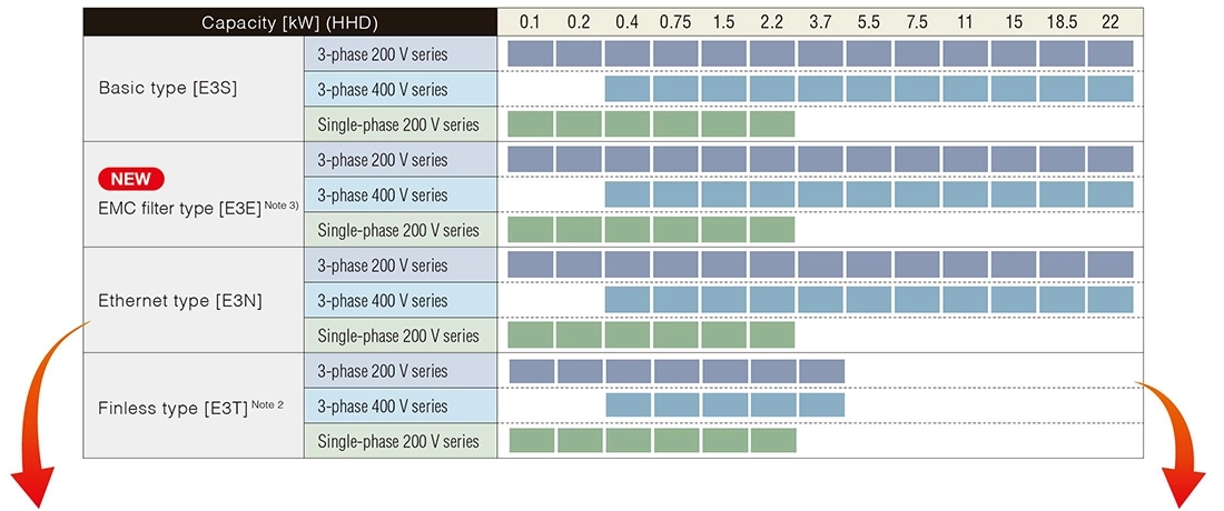
Lineup of 4 types for each power supply voltage. Supports a wide range of applications from light loads to heavy loads.
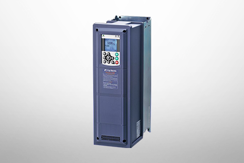
Wide Range of Power Supply Voltages and Capacity Expansion
Supports wide range of inverter power supply specifications, including 3-phase 200 V series / 400 V series and single-phase 200 V series.
Available in capacities up to 22 kW (HHD), a finless type and an Ethernet type have been added to the lineup.
Newly added to the lineup were the single-phase, 200 V, high carrier frequency normal duty (HND) type. Delivering a higher current rating
for some 400 V series, models in a wide range of capacities are selectable depending on the applications.
-
Note1
-
See the bottom of the page for details.
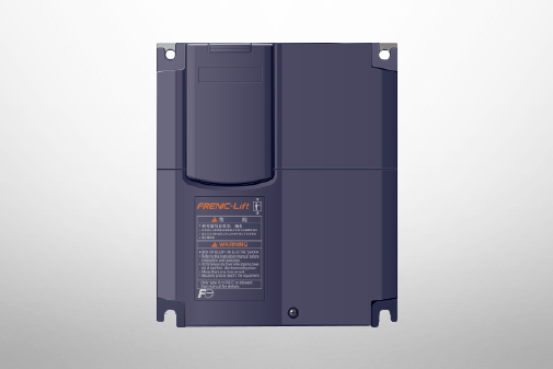
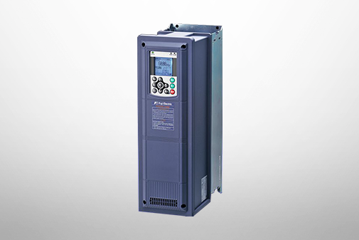
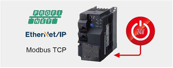
Ethernet type
Reduces tact time
Reduces tact time for setting, updating, and monitoring via the
Internet.
Shortens wiring work and reduces wiring
Shortens wiring time and reduces wiring for conventional control
signals DI/DO and AI/AO. Compact installation without requiring
option cards.
Compatible with 24 V power supplies
External 24 V power supply input enables checking communication
establishment prior to system start-up.
-
Note
-
I/O interface is inoperative.
-
Note
-
This type does not support the use of option cards.
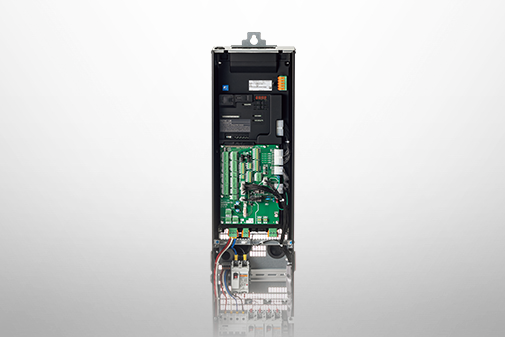
Finless type
Space savings
Absence of cooling fins enables more compact and efficient
installation of control panels and equipment.
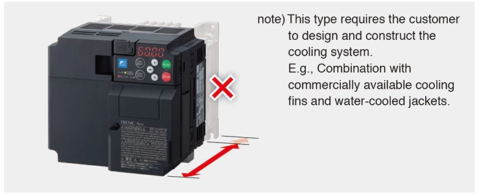
-
Note2
-
For details on the finless type, refer to the FRENIC-Ace Finless type catalog (24A1-E-0185) or consult our sales representatives.
Depth dimension (D) comparison *Three-phase 200 V series
Three-phase 400 V series rated current [A] HHD specification
Option
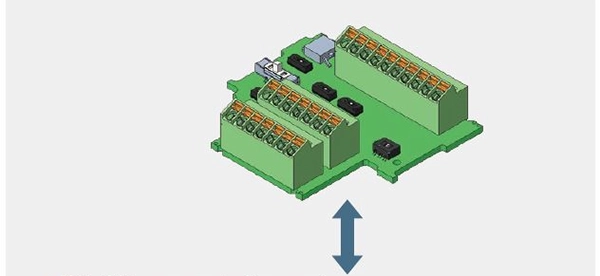
Function Expansion by Replacing the Control Terminal Board
Available in 3 types of terminal boards as options, enabling application-specific connection and I/O function expansion.
-
Note
-
For types with built-in Ethernet, the control terminal board cannot be replaced.
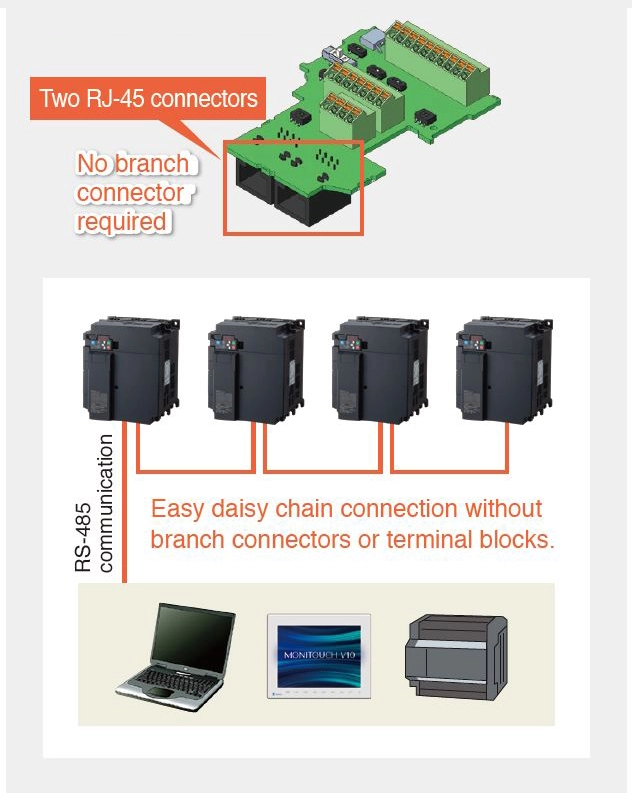
RS-485 communication card
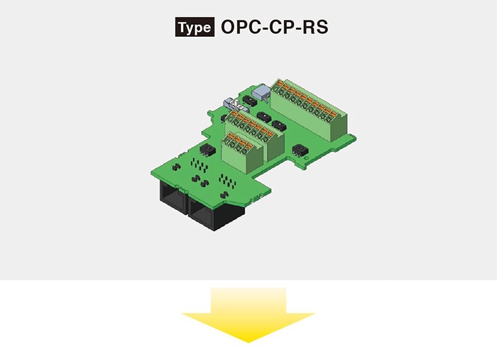
Multidrop connections
Easy connection by replacing the standard terminal board with two RS-485 port connectors (RJ-45).
Standard terminal block
RS-485 communication card
PG interface card
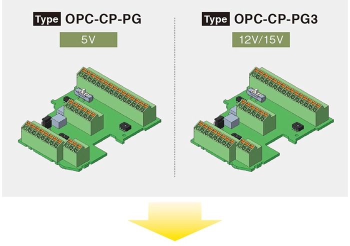
PG signal/pulse signal connection
Supports motor PG signal connection during sensor V/F control and sensor vector control, positioning, and master/follower (synchronous) operation.
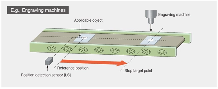
Positioning operation
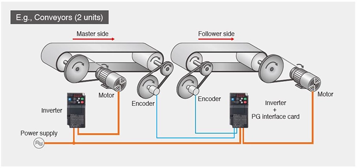
Master/follower (synchronous) operation
Easy wiring and setup, as well as remote control, for improved work efficiency.
Provides preventive and predictive maintenance functions to ensure safety.
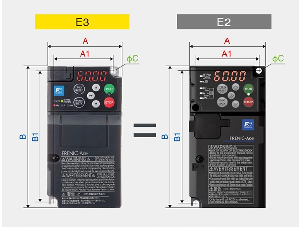
Same Mounting Dimensions
Compatible inverter body mounting dimensions.
-
Note
-
Enables conventional E2 Series replacement and installation.
-
Note
-
The depth dimension (D) is larger than the E2 Series, so please check the outline drawing.
Simple Wiring
Features a push-in terminal block for the control terminal block to dramatically improve wiring workability.
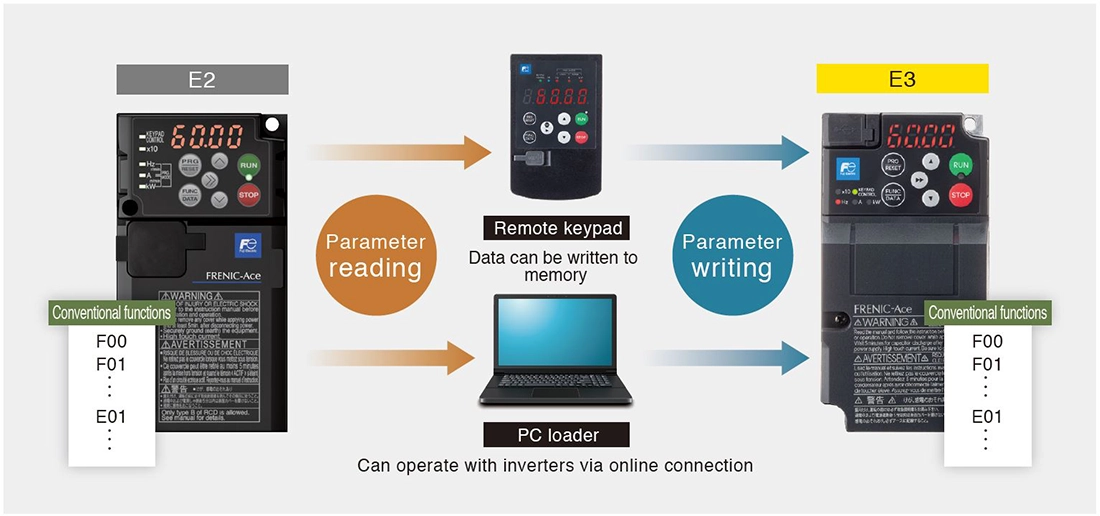
Easy Parameter Migration
Compatibility mode allows parameters read from the previous model to be written directly to the E3 Series.
Enhanced PC Loader Functions
Comes standard with a USB port (Type-C) for direct communication between the inverter and a PC or a mobile device. Parameters can be written to and read from the inverter using only bus power.
FRENIC Loader is available
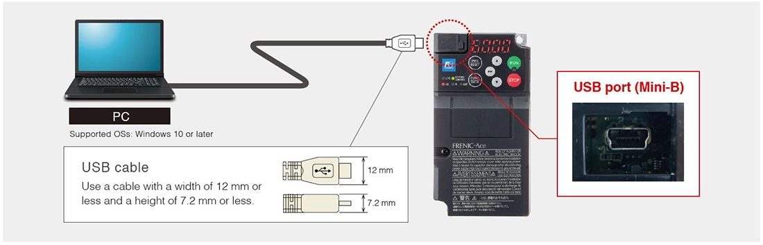
Wired connection
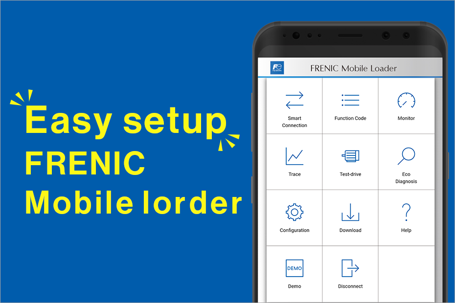
FRENIC Mobile Loader is available

-
Note
-
When using the wired connection, smartphones or tablets may not operate normally. In that case, please turn off the inverter's power supply before use.
A smartphone or tablet with the host function is required
Option
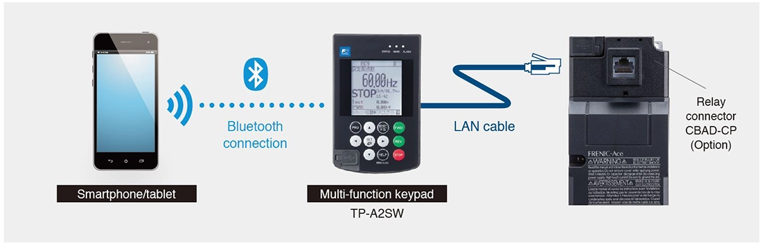
Accessible on Mobile Devices
Remote multi-function keypad (optional) enables Bluetooth communication from a smartphone or tablet to read parameters and monitor operating conditions.
Enhanced Alarm History and Traceback Functions
Alarm history can save and display data for the past 10 alarms.
-
Detailed data such as output frequency and output current for the most recent 4 alarms
-
The remaining 6 alarms only provide the alarm code and the number of consecutive occurrences.
Number of saves
-
Note
-
The numbers above indicate the number of tracebacks.
Life Expectancy Diagnosis and Maintenance Functions
The keypad and PC loader make it easy to check the status of equipment and detect problems before they occur, helping to reduce production equipment maintenance time and downtime.

Long Life Expectancy (Main Components)
Many of the serviceable parts inside the inverter have been designed to meet customer equipment maintenance cycles.
Design life 10 years


-
Note
-
Excluding finless type
-
Note1
-
The above indicates design life (calculated value) and is not a guarantee value.
-
Note2
-
The 3-phase 200 V/400 V capacity of 2.2 to 3.7 kW (HND specification) and single-phase 200 V (HND specification) are 7 years.
Other Safety and Environmental Considerations
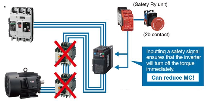
Includes safety functions
-
Compliant with European safety standards.
(EN ISO 13849-1,Cat3/PL:e IEC/EN61800-5-2: SIL3 (STO)) -
The inverter comes with a function that enables it to adapt to machine safety. This facilitates the design of main circuit switching devices for ensuring safe stoppages.
-
Note)
-
Always turn off the breaker when touching the electrical circuit during maintenance.
Improves environmental resistance
-
Further strengthens PCB coating
IEC60721-3-3/Class 3C2
-
Note
-
Salt-resistant products, etc., can be manufactured to order.

Revised European RoHS Directive
Ten environmental impact substances
-
Lead
-
Mercury
-
Cadmium
-
Hexavalent chromium
-
Polybrominated biphenyl (PBB)
-
Polybrominated diphenyl ether (PBDE)
-
Di-2-ethylhexyl phthalate (DEHP)
-
Butyl benzyl phthalate (BBP)
-
Di-n-butyl phthalate (DBP)
-
Diisobutyl phthalate (DIBP)
Globally compliant
Compliant with overseas safety standards.
| European regions England |
EC directive |
| United States Canada |
UL standard/cUL standard |
| Korea |
KC certification |
AC Drives (Low Voltage) Support
Download documents
Column
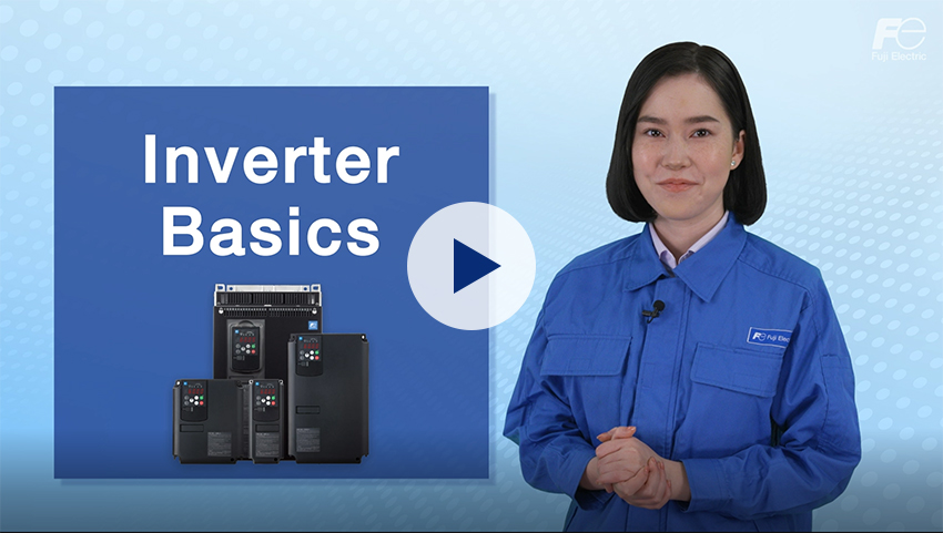
Understanding application, benefits, basic structure, case study, types, and Fuji Electric's inverters with this video.
December 27,2021

Understanding the basics: Differences between inverters and converters
January 20,2021

How and what does an inverter take control of? A brief explanation to grasp the basic structure.
January 20,2021

The fundamentals of inverters and their uses.
January 20,2021