FRENIC-Mini
Standard Specifications | Basic type
-
Standard Specifications Basic type
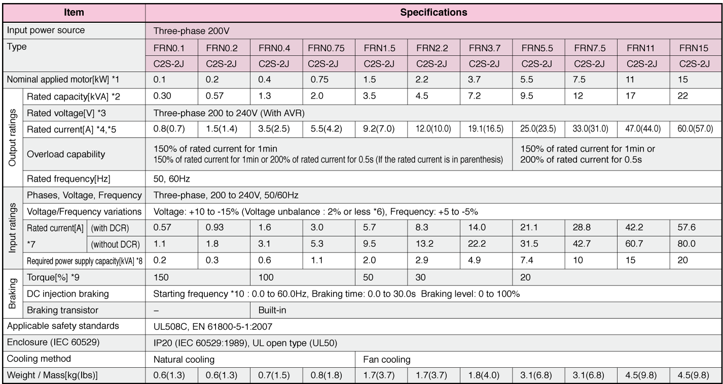
Three-phase 200V (Basic type)
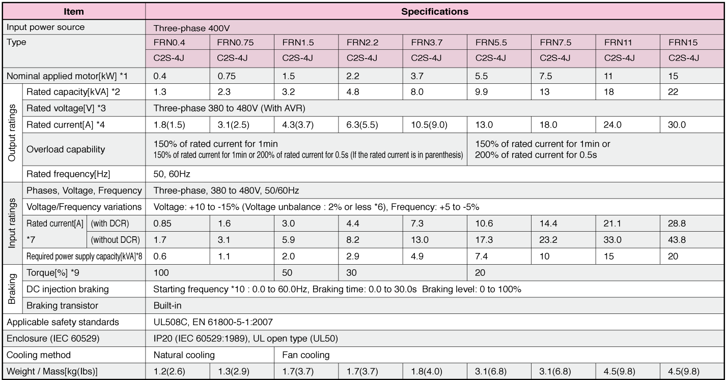
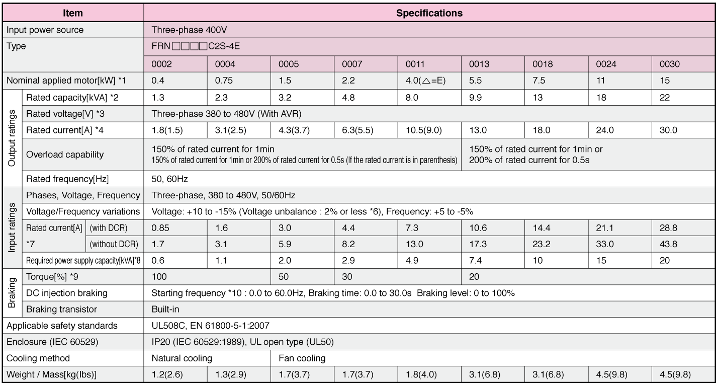
Three-phase 400V (Basic type)
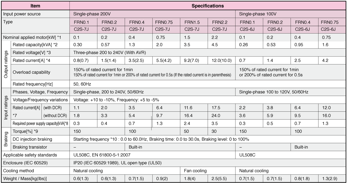
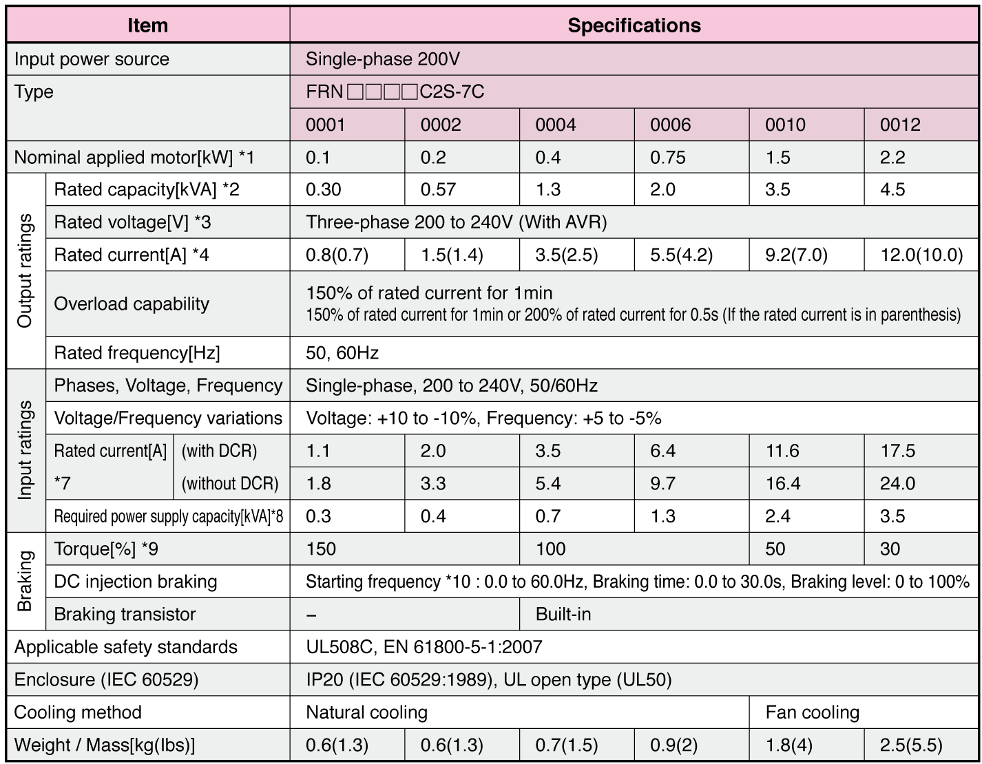
Single-phase 200V/100V (Basic type)
-
Note1
-
Fuji 4-pole standard motors
-
Note2
-
Assuming the rated output voltage as 220 V for three-phase 200 V series.
-
Note3
-
Output voltages cannot exceed the power supply voltage.
-
Note4
-
FRN0001C2S-2J~ FRN0020C2S-2J, FRN0002C2S-4J~ FRN0011C2S-4J: The load shall be reduced so that the continuous operating current is the rated current in parenthesis or less if the carrier frequency is set to 3kHz or above or ambient temperature exceeds 40°C (104°F).
-
Note5
-
FRN0025C2S-2J~ FRN0060C2S-2J: The load shall be reduced so that the continuous operating current is the rated current in parenthesis or less if the carrier frequency is set to 4kHz or above or ambient temperature exceeds 40°C (104°F).
-
Note6
-
Interphase voltage unbalance [%] = (Max. voltage [V]-Min. voltage [V]) / (3-phase average voltage [V]) × 67 (Refer to IEC 61800-3:2004)
If this value is 2 to 3%, use an optional AC reactor (ACR).
-
Note7
-
Estimated value to apply when the power supply capacity is 500 kVA (inverter capacity x 10 when the inverter capacity exceeds 50 kVA) and the inverter is connected to the %X = 5% power supply.
-
Note8
-
Values to apply when a DC reactor (DCR) is used.
-
Note9
-
Average braking torque to apply when the motor running alone decelerates from 60 Hz with the AVR control being OFF. (It varies with the efficiency of the motor.)
-
Note10
-
Available only for induction motor drive.
-
Note
-
When driven by 100 VAC, the single-phase 100 V class series of inverters limits their shaft output and maximum output torque as listed below. This is to prevent their output voltage from decreasing when load is applied.
-
Standard Specifications Basic type
Three-phase 400V (Basic type)
Single-phase 200V/100V (Basic type)

-
Note1
-
Fuji 4-pole standard motors
-
Note2
-
Assuming the rated output voltage as 220 V for three-phase 200 V series.
-
Note3
-
Output voltages cannot exceed the power supply voltage.
-
Note4
-
FRN0001C2S-2E~ FRN0020C2S-2E, FRN0002C2S-4E~ FRN0011C2S-4E: The load shall be reduced so that the continuous operating current is the rated current in parenthesis or less if the carrier frequency is set to 3kHz or above or ambient temperature exceeds 40°C (104°F).
-
Note5
-
FRN0025C2S-2E~ FRN0060C2S-2E: The load shall be reduced so that the continuous operating current is the rated current in parenthesis or less if the carrier frequency is set to 4kHz or above or ambient temperature exceeds 40°C (104°F).
-
Note6
-
Interphase voltage unbalance [%] = (Max. voltage [V]-Min. voltage [V]) / (3-phase average voltage [V]) × 67 (Refer to IEC 61800-3:2004)
If this value is 2 to 3%, use an optional AC reactor (ACR).
-
Note7
-
Estimated value to apply when the power supply capacity is 500 kVA (inverter capacity x 10 when the inverter capacity exceeds 50 kVA) and the inverter is connected to the %X = 5% power supply.
-
Note8
-
Values to apply when a DC reactor (DCR) is used.
-
Note9
-
Average braking torque to apply when the motor running alone decelerates from 60 Hz with the AVR control being OFF. (It varies with the efficiency of the motor.)
-
Note10
-
Available only for induction motor drive.
-
Note
-
When driven by 100 VAC, the single-phase 100 V class series of inverters limits their shaft output and maximum output torque as listed below. This is to prevent their output voltage from decreasing when load is applied.
-
Standard Specifications Basic type
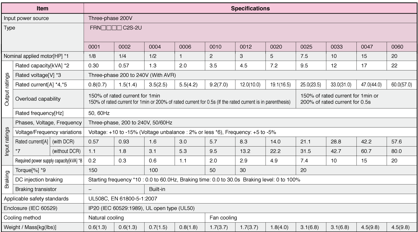
Three-phase 200V (Basic type)
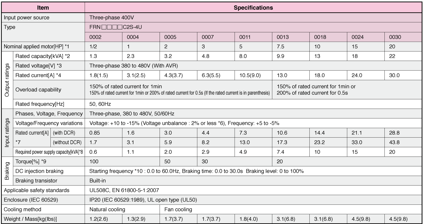
Three-phase 400V (Basic type)
Single-phase 200V/100V (Basic type)

-
Note1
-
Fuji 4-pole standard motors
-
Note2
-
Assuming the rated output voltage as 220 V for three-phase 200 V series.
-
Note3
-
Output voltages cannot exceed the power supply voltage.
-
Note4
-
FRN0001C2S-2U~ FRN0020C2S-2U, FRN0002C2S-4U~ FRN0011C2S-4U: The load shall be reduced so that the continuous operating current is the rated current in parenthesis or less if the carrier frequency is set to 3kHz or above or ambient temperature exceeds 40°C (104°F).
-
Note5
-
FRN0025C2S-2U~ FRN0060C2S-2U: The load shall be reduced so that the continuous operating current is the rated current in parenthesis or less if the carrier frequency is set to 4kHz or above or ambient temperature exceeds 40°C (104°F).
-
Note6
-
Interphase voltage unbalance [%] = (Max. voltage [V]-Min. voltage [V]) / (3-phase average voltage [V]) × 67 (Refer to IEC 61800-3:2004)
If this value is 2 to 3%, use an optional AC reactor (ACR).
-
Note7
-
Estimated value to apply when the power supply capacity is 500 kVA (inverter capacity x 10 when the inverter capacity exceeds 50 kVA) and the inverter is connected to the %X = 5% power supply.
-
Note8
-
Values to apply when a DC reactor (DCR) is used.
-
Note9
-
Average braking torque to apply when the motor running alone decelerates from 60 Hz with the AVR control being OFF. (It varies with the efficiency of the motor.)
-
Note10
-
Available only for induction motor drive.
-
Note
-
When driven by 100 VAC, the single-phase 100 V class series of inverters limits their shaft output and maximum output torque as listed below. This is to prevent their output voltage from decreasing when load is applied.
-
Standard Specifications Basic type
Three-phase 400V (Basic type)
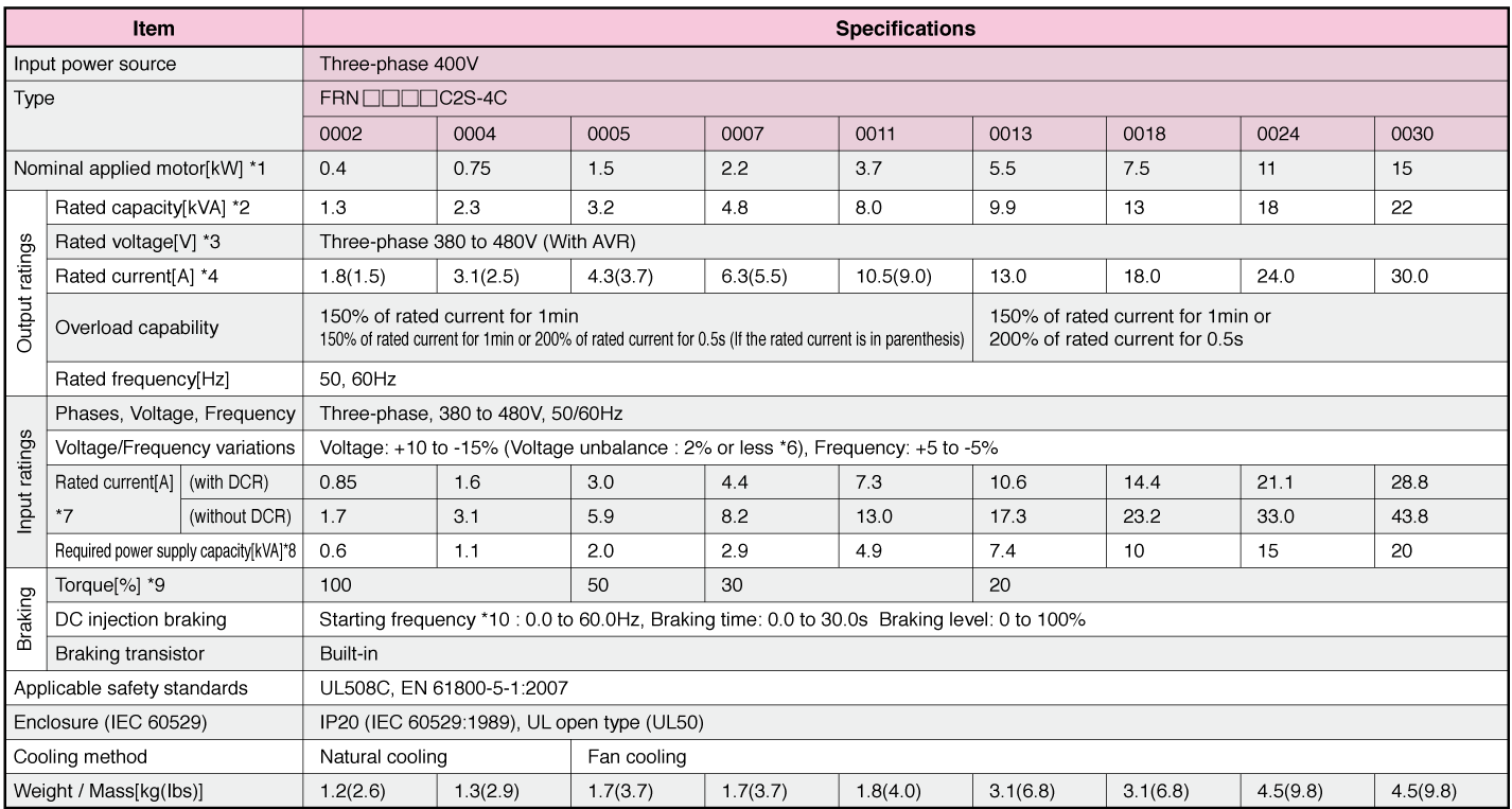
Single-phase 200V/100V (Basic type)
-
Note1
-
Fuji 4-pole standard motors
-
Note2
-
Assuming the rated output voltage as 220 V for three-phase 200 V series.
-
Note3
-
Output voltages cannot exceed the power supply voltage.
-
Note4
-
FRN0001C2S-2C~ FRN0020C2S-2C, FRN0002C2S-4C~ FRN0011C2S-4C: The load shall be reduced so that the continuous operating current is the rated current in parenthesis or less if the carrier frequency is set to 3kHz or above or ambient temperature exceeds 40°C (104°F).
-
Note5
-
FRN0025C2S-2C~ FRN0060C2S-2C: The load shall be reduced so that the continuous operating current is the rated current in parenthesis or less if the carrier frequency is set to 4kHz or above or ambient temperature exceeds 40°C (104°F).
-
Note6
-
Interphase voltage unbalance [%] = (Max. voltage [V]-Min. voltage [V]) / (3-phase average voltage [V]) × 67 (Refer to IEC 61800-3:2004)
If this value is 2 to 3%, use an optional AC reactor (ACR).
-
Note7
-
Estimated value to apply when the power supply capacity is 500 kVA (inverter capacity x 10 when the inverter capacity exceeds 50 kVA) and the inverter is connected to the %X = 5% power supply.
-
Note8
-
Values to apply when a DC reactor (DCR) is used.
-
Note9
-
Average braking torque to apply when the motor running alone decelerates from 60 Hz with the AVR control being OFF. (It varies with the efficiency of the motor.)
-
Note10
-
Available only for induction motor drive.
-
Note
-
When driven by 100 VAC, the single-phase 100 V class series of inverters limits their shaft output and maximum output torque as listed below. This is to prevent their output voltage from decreasing when load is applied.
-
Standard Specifications Basic type
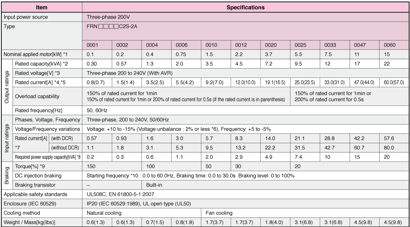
Three-phase 200V (Basic type)
Three-phase 400V (Basic type)

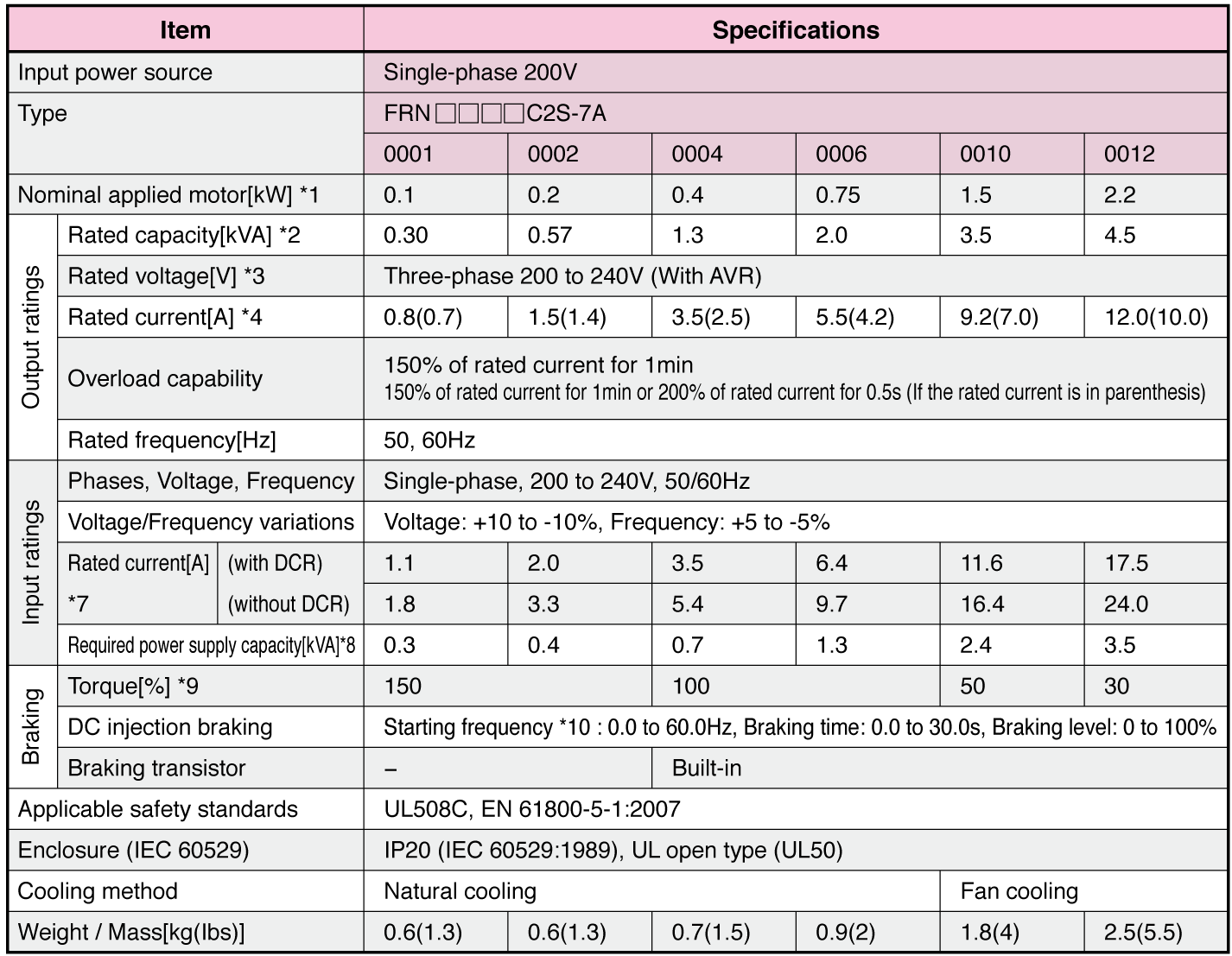
Single-phase 200V/100V (Basic type)
-
Note1
-
Fuji 4-pole standard motors
-
Note2
-
Assuming the rated output voltage as 220 V for three-phase 200 V series.
-
Note3
-
Output voltages cannot exceed the power supply voltage.
-
Note4
-
FRN0001C2S-2A~ FRN0020C2S-2A, FRN0002C2S-4A~ FRN0011C2S-4A: The load shall be reduced so that the continuous operating current is the rated current in parenthesis or less if the carrier frequency is set to 3kHz or above or ambient temperature exceeds 40°C (104°F).
-
Note5
-
FRN0025C2S-2A~ FRN0060C2S-2A: The load shall be reduced so that the continuous operating current is the rated current in parenthesis or less if the carrier frequency is set to 4kHz or above or ambient temperature exceeds 40°C (104°F).
-
Note6
-
Interphase voltage unbalance [%] = (Max. voltage [V]-Min. voltage [V]) / (3-phase average voltage [V]) × 67 (Refer to IEC 61800-3:2004)
If this value is 2 to 3%, use an optional AC reactor (ACR).
-
Note7
-
Estimated value to apply when the power supply capacity is 500 kVA (inverter capacity x 10 when the inverter capacity exceeds 50 kVA) and the inverter is connected to the %X = 5% power supply.
-
Note8
-
Values to apply when a DC reactor (DCR) is used.
-
Note9
-
Average braking torque to apply when the motor running alone decelerates from 60 Hz with the AVR control being OFF. (It varies with the efficiency of the motor.)
-
Note10
-
Available only for induction motor drive.
-
Note
-
When driven by 100 VAC, the single-phase 100 V class series of inverters limits their shaft output and maximum output torque as listed below. This is to prevent their output voltage from decreasing when load is applied.
This type is not available in this region.
If you need more information for this products, please contact us through the inquiry form.
-
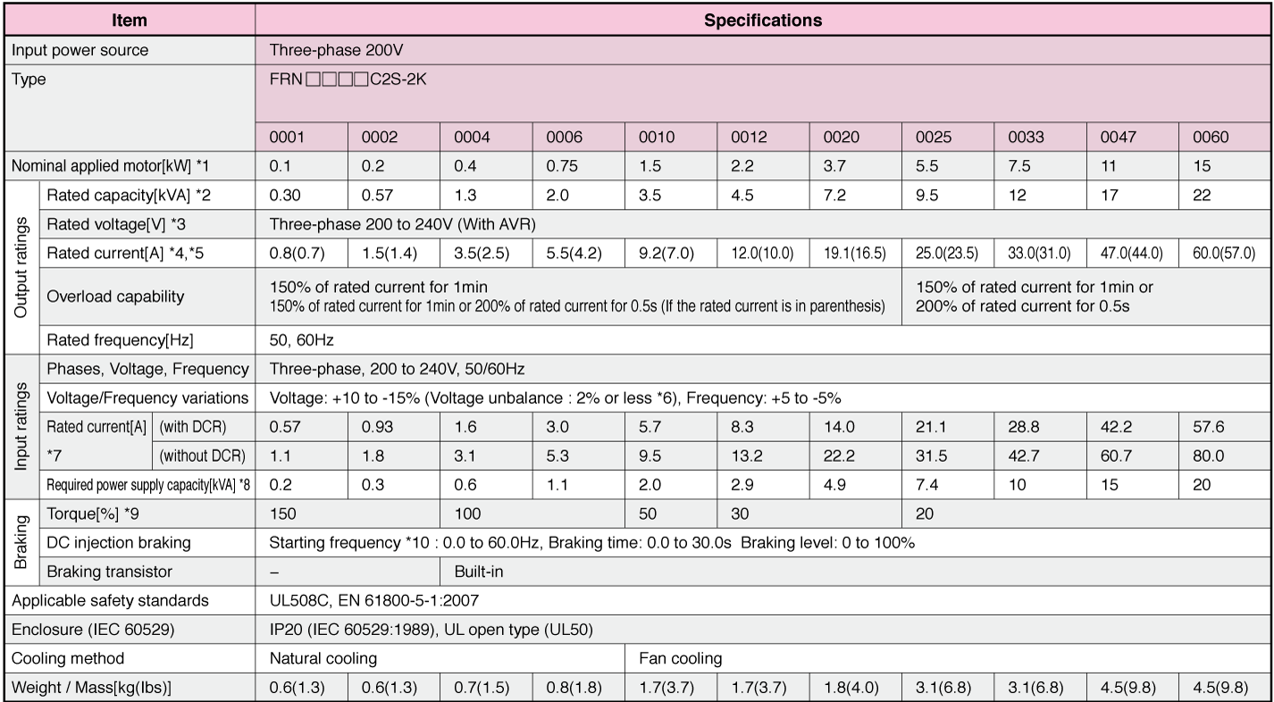
Standard Specifications Basic type
Three-phase 200V (Basic type)
Three-phase 200V (Basic type)

-
Note1
-
Fuji 4-pole standard motors
-
Note2
-
Assuming the rated output voltage as 220 V for three-phase 200 V series.
-
Note3
-
Output voltages cannot exceed the power supply voltage.
-
Note4
-
FRN0001C2S-2K~ FRN0020C2S-2K, FRN0002C2S-4K~ FRN0011C2S-4K: The load shall be reduced so that the continuous operating current is the rated current in parenthesis or less if the carrier frequency is set to 3kHz or above or ambient temperature exceeds 40°C (104°F).
-
Note5
-
FRN0025C2S-2K~ FRN0060C2S-2K: The load shall be reduced so that the continuous operating current is the rated current in parenthesis or less if the carrier frequency is set to 4kHz or above or ambient temperature exceeds 40°C (104°F).
-
Note6
-
Interphase voltage unbalance [%] = (Max. voltage [V]-Min. voltage [V]) / (3-phase average voltage [V]) × 67 (Refer to IEC 61800-3:2004)
If this value is 2 to 3%, use an optional AC reactor (ACR).
-
Note7
-
Estimated value to apply when the power supply capacity is 500 kVA (inverter capacity x 10 when the inverter capacity exceeds 50 kVA) and the inverter is connected to the %X = 5% power supply.
-
Note8
-
Values to apply when a DC reactor (DCR) is used.
-
Note9
-
Average braking torque to apply when the motor running alone decelerates from 60 Hz with the AVR control being OFF. (It varies with the efficiency of the motor.)
-
Note10
-
Available only for induction motor drive.
-
Note
-
When driven by 100 VAC, the single-phase 100 V class series of inverters limits their shaft output and maximum output torque as listed below. This is to prevent their output voltage from decreasing when load is applied.