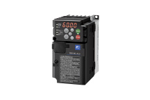
ALPHA5 | Servo amplifier | VE Type

Specification
Common specifications
100V series
| Applicable motor rated speed | 3000r/min | |||||
|---|---|---|---|---|---|---|
| Applicable motor output [kW] | 0.05 | 0.1 | 0.2 | 0.375 | ||
| Amplifier type RYT□□□ D5-VE6 |
500 | 101 | 201 | 401 | ||
| Outer frame number | Frame 1 | Frame 2 | Frame 3 | |||
| Mass [kg] | 0.9 | 1.1 | 1.3 | |||
| Open / self-cooling | Open / forced air cooling | |||||
| Power supply | Main power supply | Phase | Single-phase | |||
| Voltage frequency | AC100 to 120V 50/60Hz | |||||
| Allowable voltage fluctuation | AC85 to 132V | |||||
| Control power supply | Phase | Single-phase | ||||
| Voltage frequency | AC100 to 120V 50/60Hz | |||||
| Allowable voltage fluctuation | AC85 to 132V | |||||
| Control system | IGBT PWM sinusoidal PWM drive | |||||
| Max voltage for regenerative resistance [W] | Built-in resistor | - | - | 8 | 20 | |
| External resistor *1 | 17 | 17 | 25 | 25 | ||
| Dynamic brake | Built-in *2 | |||||
| Feedback | 18-bit serial encoder (absolute/incremental), 20-bit serial encoder (incremental) | |||||
| Overload capability | 300% / 3 sec. | |||||
| Speed fluctuation ratio | Load fluctuation | Within ±1 r/min (load fluctuation 0 to 100%) | ||||
| Power supply fluctuation | Within ±1 r/min (power supply fluctuation -10 to +10%) | |||||
| Temperature fluctuation | Within ±0.2% (25 ±10°C at rated operation speed and analog input operation) | |||||
| Capability and function | Speed control function | Closed loop control with speed adjuster, acceleration/deceleration time setting, manual feed rate/max. rotation speed, etc. | ||||
| Position control function | Closed loop control with position adjuster, electronic gear, output pulse setting, feed forward, homing, interrupt positioning, etc. | |||||
| Torque control function | Closed loop control with current adjuster (proportional open loop control of current and torque), torque limit, speed limit at torque control, etc. | |||||
| Accessory functions | Easy tuning, profile operation, sequence test mode, auto tuning, auto notch filter, vibration suppressing online learning, etc. | |||||
| Protective function (Alarm indication) | Overcurrent(oc1, oc2), Overspeed(oS), Control power undervoltage(Lvc), Overvoltage(Hv), Encoder trouble(Et1, Et2), Circuit trouble(ct), Memory Error(dE), Fuse Broken(Fb), Motor Combination Error(cE), Braking transistor overheat(tH), Encoder Communication error(Ec), CONT(Control signal) Error(ctE), Overload(oL1, oL2), Main power undervoltage(LvP), Braking resistor overheat(rH1, rH2, rH3), Deviation overflow(oF), Amplifier overheat(AH), Encoder overheat(EH), Absolute data Lost(dL1, dL2, dL3), Multi-turn data over flow(AF), Initial Error(iE), Command pulse Frequency Error(HF) | |||||
| 6-digit alphanumeric display with 7-segment LED 4 operation switches Analog monitor connector (CN6), status indication LED |
||||||
| Working conditions | Installation place | Indoors (free from direct sunshine), altitude ≦ 1000m, free from corrosive and flammable gases, oil mist and dust In case of compliance with CE marking Models compliant with EU directive: pollution degree 2, over voltage category III |
||||
| Temperature/humidity | -10 to 55°C/10 to 90%RH (without condensation) | |||||
| Vibration / shock resistance | 4.9m/s2/19.6m/s2 | |||||
| Standards | UL/cUL (UL508c), CE marking (low voltage directive EN61800-5-1) (acquisition being applied for model of 2.0kW or more), RoHS directive | |||||
- *1:The figure is data determined when the amplifier is connected with an external resistor dedicated for each model.
- *2:We will accept custom orders for models without dynamic brake.

200V series
| Applicable motor rated speed | 3000r/min | ||||||||||||
|---|---|---|---|---|---|---|---|---|---|---|---|---|---|
| Applicable motor output [kW] | 0.05 | 0.1 | 0.2 | 0.4 | 0.75 | 1 | 1.5 | 2.0 | 3.0 | 4.0 | 5.0 | ||
| Amplifier type RYT□□□ D5-VE2 |
500 | 101 | 201 | 401 | 751 | 102 | 152 | 202 | 302 | 402 | 502 | ||
| Outer frame number | Frame 1 | Frame 2 | Frame 3 | Frame 4 | Frame 5 | Frame 6 | |||||||
| Mass [kg] | 0.9 | 1.1 | 1.3 | 1.5 | 2.6 | 3.8 | |||||||
| Open / self-cooling | Open / forced air cooling | ||||||||||||
| Power supply | Main power supply | Phase | Single-phase, 3-phase | 3-phase | |||||||||
| Voltage frequency | AC200 to 240V 50/60Hz | ||||||||||||
| Allowable voltage fluctuation | 3-phase: AC170 to 262V, Single-phase: AC190 to 262V | ||||||||||||
| Control power supply | Phase | Single-phase | |||||||||||
| Voltage frequency | AC200 to 240V 50/60Hz | ||||||||||||
| Allowable voltage fluctuation | AC170 to 262V | ||||||||||||
| Control system | IGBT PWM sinusoidal PWM drive | ||||||||||||
| Max voltage for regenerative resistance [W] | Built-in resistor | - | - | - | 8 | 20 | 20 | 20 | 30 | 30 | 60 | 60 | |
| External resistor *1 | 17 | 17 | 17 | 17 | 50 | 50 | 50 | 260 | 260 | 300 | 300 | ||
| Dynamic brake | Built-in *2 | ||||||||||||
| Feedback | 18-bit serial encoder (absolute/incremental), 20-bit serial encoder (incremental) | ||||||||||||
| Overload capability | 300% / 3 sec. | ||||||||||||
| Speed fluctuation ratio | Load fluctuation | Within ±1 r/min (load fluctuation 0 to 100%) | |||||||||||
| Power supply fluctuation | Within ±1 r/min (power supply fluctuation -10 to +10%) | ||||||||||||
| Temperature fluctuation | Within ±0.2% (25 ±10°C at rated operation speed and analog input operation) | ||||||||||||
| Capability and function | Speed control function | Closed loop control with speed adjuster, acceleration/deceleration time setting, manual feed rate/max. rotation speed, etc. | |||||||||||
| Position control function | Closed loop control with position adjuster, electronic gear, output pulse setting, feed forward, homing, interrupt positioning, etc. | ||||||||||||
| Torque control function | Closed loop control with current adjuster (proportional open loop control of current and torque), torque limit, speed limit at torque control, etc. | ||||||||||||
| Accessory functions | Easy tuning, profile operation, sequence test mode, auto tuning, auto notch filter, vibration suppressing online learning, etc. | ||||||||||||
| Protective function (Alarm indication) | Overcurrent(oc1, oc2), Overspeed(oS), Control power undervoltage(Lvc), Overvoltage(Hv), Encoder trouble(Et1, Et2), Circuit trouble(ct), Memory Error(dE), Fuse Broken(Fb), Motor Combination Error(cE), Braking transistor overheat(tH), Encoder Communication error(Ec), CONT(Control signal) Error(ctE), Overload(oL1, oL2), Main power undervoltage(LvP), Braking resistor overheat(rH1, rH2, rH3), Deviation overflow(oF), Amplifier overheat(AH), Encoder overheat(EH), Absolute data Lost(dL1, dL2, dL3), Multi-turn data over flow(AF), Initial Error(iE), Command pulse Frequency Error(HF) | ||||||||||||
| 6-digit alphanumeric display with 7-segment LED 4 operation switches Analog monitor connector (CN6), status indication LED |
|||||||||||||
| Working conditions | Installation place | Indoors (free from direct sunshine), altitude ≦ 1000m, free from corrosive and flammable gases, oil mist and dust In case of compliance with CE marking Models compliant with EU directive: pollution degree 2, over voltage category III |
|||||||||||
| Temperature/humidity | -10 to 55°C/10 to 90%RH (without condensation) | ||||||||||||
| Vibration / shock resistance | 4.9m/s2/19.6m/s2 | ||||||||||||
| Standards | UL/cUL (UL508c), CE marking (low voltage directive EN61800-5-1) (acquisition being applied for model of 2.0kW or more), RoHS directive | ||||||||||||
- *1:The figure is data determined when the amplifier is connected with an external resistor dedicated for each model.
- *2:We will accept custom orders for models without dynamic brake.
| Applicable motor rated speed | 2000r/min | 1500r/min | ||||||||
|---|---|---|---|---|---|---|---|---|---|---|
| Applicable motor output [kW] | 0.5 | 0.75 | 1.0 | 1.5 | 2.0 | 0.5 | 0.85 | 1.3 | ||
| Amplifier type RYT□□□ | C5-VE2 | 501 | 751 | 102 | 152 | 202 | ||||
| B5-VE2 | 501 | 851 | 132 | |||||||
| Outer frame number | Frame 3 | Frame 4 | Frame 5 | Frame 3 | Frame 4 | Frame 5 | ||||
| Mass [kg] | 1.3 | 1.5 | 2.9 | 1.3 | 1.5 | 2.9 | ||||
| Open / forced air cooling | Open / forced air cooling | |||||||||
| Power supply | Main power supply | Phase | Single-phase, 3-phase | 3-phase | Single-phase, 3-phase | 3-phase | ||||
| Voltage frequency | AC200 to 240V 50/60Hz | |||||||||
| Allowable voltage fluctuation | 3-phase: AC170 to 262V, Single-phase: AC190 to 262V | |||||||||
| Control power supply | Phase | Single-phase | ||||||||
| Voltage frequency | AC200 to 240V 50/60Hz | |||||||||
| Allowable voltage fluctuation | AC170 to 262V | |||||||||
| Control system | IGBT PWM sinusoidal PWM drive | |||||||||
| Max voltage for regenerative resistance [W] | Built-in resistor | 20 | 20 | 20 | 30 | 30 | 20 | 20 | 30 | |
| External resistor *1 | 50 | 50 | 50 | 260 | 260 | 50 | 50 | 260 | ||
| Dynamic brake | Built-in *2 | |||||||||
| Feedback | 18-bit serial encoder (absolute/incremental), 20-bit serial encoder (incremental) | |||||||||
| Overload capability | 300% / 3 sec. | |||||||||
| Speed fluctuation ratio | Load fluctuation | Within ±1 r/min (load fluctuation 0 to 100%) | ||||||||
| Power supply fluctuation | Within ±1 r/min (power supply fluctuation -10 to +10%) | |||||||||
| Temperature fluctuation | Within ±0.2% (25 ±10°C at rated operation speed and analog input operation) | |||||||||
| Capability and function | Speed control function | Closed loop control with speed adjuster, acceleration/deceleration time setting, manual feed rate/max. rotation speed, etc. | ||||||||
| Position control function | Closed loop control with position adjuster, electronic gear, output pulse setting, feed forward, homing, interrupt positioning, etc. | |||||||||
| Torque control function | Closed loop control with current adjuster (proportional open loop control of current and torque), torque limit, speed limit at torque control, etc. | |||||||||
| Accessory functions | Easy tuning, profile operation, sequence test mode, auto tuning, auto notch filter, vibration suppressing online learning, etc. | |||||||||
| Protective function (Alarm indication) | Overcurrent(oc1, oc2), Overspeed(oS), Control power undervoltage(Lvc), Overvoltage(Hv), Encoder trouble(Et1, Et2), Circuit trouble(ct), Memory Error(dE), Fuse Broken(Fb), Motor Combination Error(cE), Braking transistor overheat(tH), Encoder Communication error(Ec), CONT(Control signal) Error(ctE), Overload(oL1, oL2), Main power undervoltage(LvP), Braking resistor overheat(rH1, rH2, rH3), Deviation overflow(oF), Amplifier overheat(AH), Encoder overheat(EH), Absolute data Lost(dL1, dL2, dL3), Multi-turn data over flow(AF), Initial Error(iE), Command pulse Frequency Error(HF) | |||||||||
| 6-digit alphanumeric display with 7-segment LED 4 operation switches Analog monitor connector (CN6), status indication LED |
||||||||||
| Working conditions | Installation place | Indoors (free from direct sunshine), altitude ≦ 1000m, free from corrosive and flammable gases, oil mist and dust In case of compliance with CE marking Models compliant with EU directive: pollution degree 2, over voltage category III |
||||||||
| Temperature/humidity | -10 to 55°C/10 to 90%RH (without condensation) | |||||||||
| Vibration / shock resistance | 4.9m/s2/19.6m/s2 | |||||||||
| Standards | UL/cUL (UL508c), CE marking (low voltage directive EN61800-5-1) (acquisition being applied for model of 2.0kW or more), RoHS directive | |||||||||
- *1:The figure is data determined when the amplifier is connected with an external resistor dedicated for each model.
- *2:We will accept custom orders for models without dynamic brake.
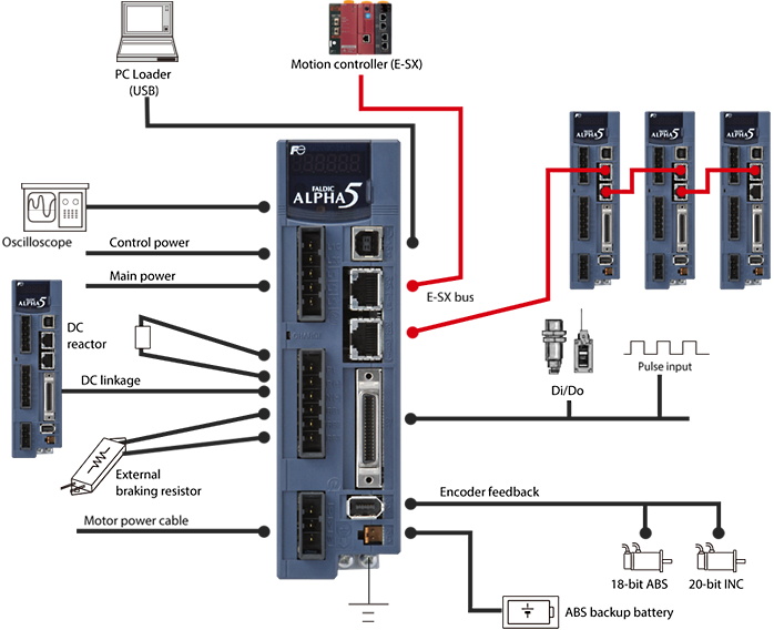
Outline of system configuration
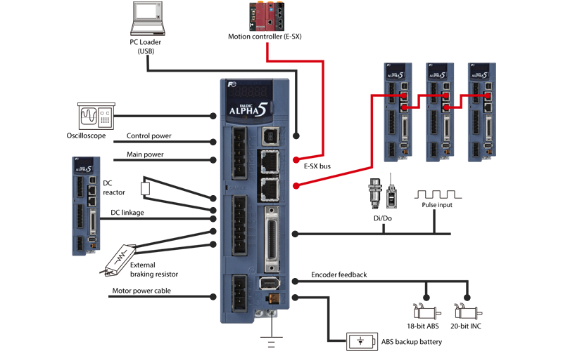
Interface specifications
| Item | Specifications | |
|---|---|---|
| Command interface | Position control | E-SX bus: IQ area |
| Speed control | E-SX bus: IQ area | |
| Torque control | E-SX bus: IQ area | |
| Communication interface | E-SX bus (for command interface, parameter editing, monitor) | |
| Original Fuji protocol | ||
| 100 Mbps, connection of up to 238 axes | ||
| Terminal name | Symbol | Specifications |
|---|---|---|
| Pulse input | CA,*CA CB,*CB |
Pulse input when using high-speed counter function (VE type), pulse input when using position control (LE type) Differential input: max. input frequency ≤ 1.0MHz Open collector input: max. input frequency ≤ 200kHz (With signals of 90-degree phase difference, the above relationship is true for a four-fold frequency.) Pulse format: ・Command pulse/command code ・Forward/reverse pulse ・Two signals at 90-degree phase difference Select one of these formats with a parameter setting. |
| PPI | Pull-up power input when open collector input (24 VDC ±10%) |
|
| Pulse output | FFA,*FFA FFB,*FFB |
Differential output: max. output frequency ≤ 1MHz Two signals at 90-degree phase difference Pulse output count setting n pulses/rev: 16 ≤ n ≤ 262144 |
| FFZ,*FFZ | Differential output: 1 pulse/rev | |
| FZ | Open collector output: 1 pulse/rev | |
| M5 | Reference potential (0 V) | |
| Analog monitor voltage output | MON1 MON2 |
0 V to ±10 VDC Resolution: 14 bits / ± full scale Output data depends on internal parameters. |
| M5 | M5 is reference potential (0 V) | |
| Common for sequence l/0 | COMIN | Common for sequence input signal |
| COMOUT | Common for sequence output signal | |
| Sequence input signal | CONT1 to CONT5 |
ON upon short circuit across contacts, OFF when open circuit 12 VDC - 10% to 24 VDC + 10% Current consumption: 20mA (per contact; used at 24 VDC circuit voltage) Function of each signal depends on parameter setting Compatible with both sink and source input methods |
| Sequence output signal | OUT1 to OUT2 |
Short circuit when ON, open circuit when OFF 30 VDC / 50mA (max.) Function of each signal depends on parameter setting Compatible with both sink and source output methods |
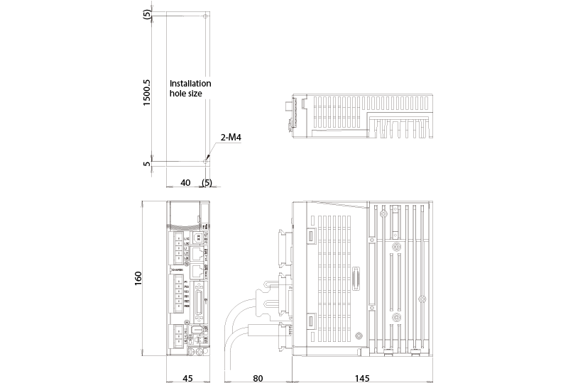
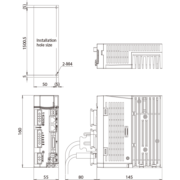
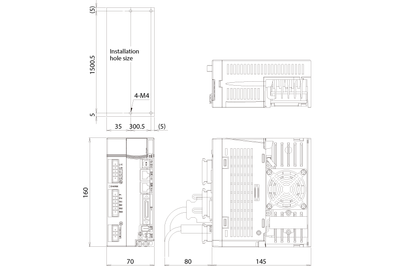
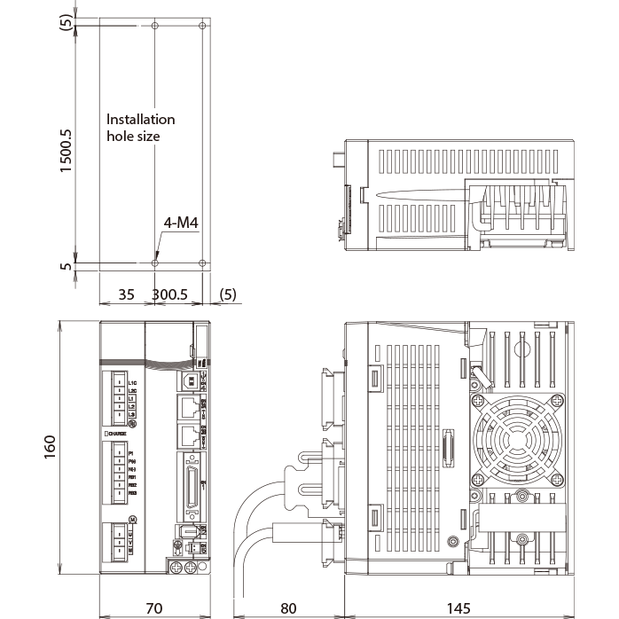
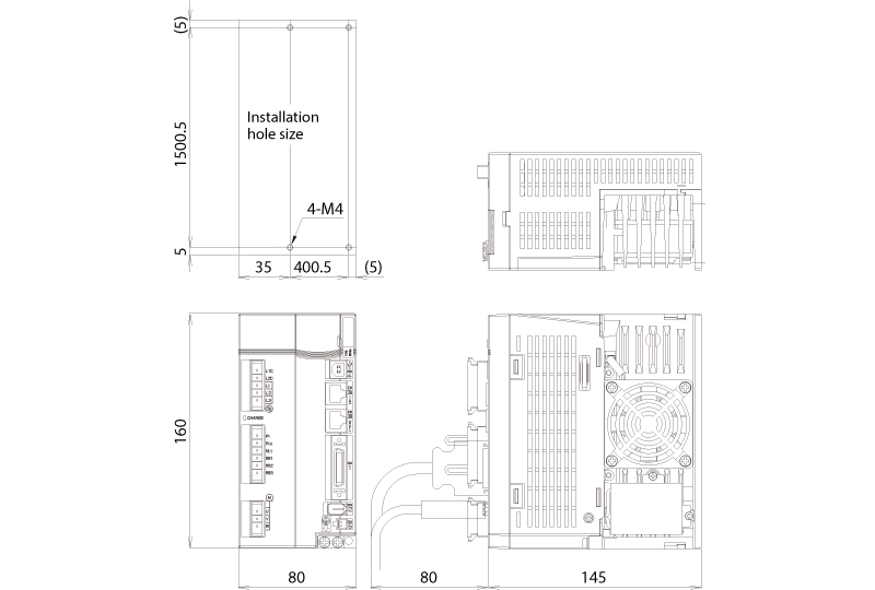
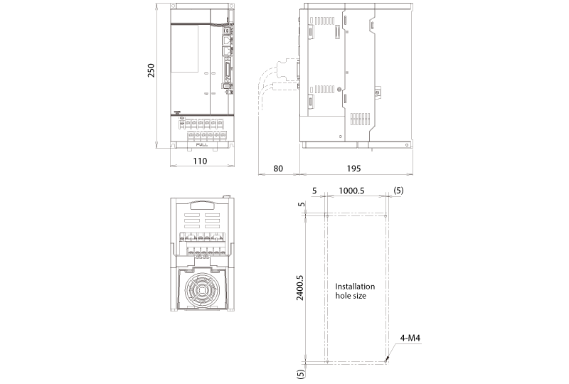
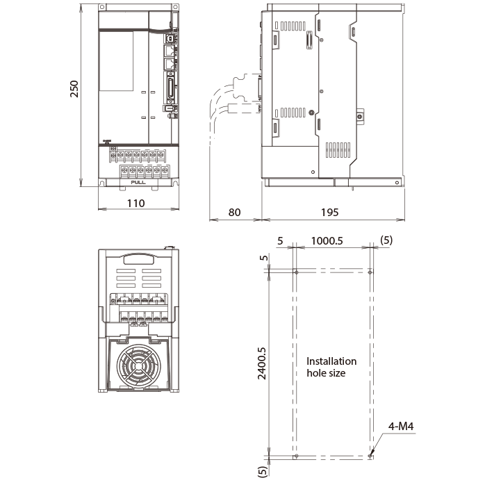
External Dimensions
The following outline drawings are for the VS type and LS type servo amplifiers. The right-left directions of the E-SX bus connectors (CN3A and CN3B) are reversed on the VE type and LE type servo amplifiers.
Frame 1
| Power supply | Rated speed | Applicable motor output | Type |
|---|---|---|---|
| 100V series | 3000r/min | 0.05kW | RYT500D5-VE6 |
| 0.1kW | RYT101D5-VE6 | ||
| 200V series | 0.05kW | RYT500D5-VE2 | |
| 0.1kW | RYT101D5-VE2 | ||
| 0.2kW | RYT201D5-VE2 |
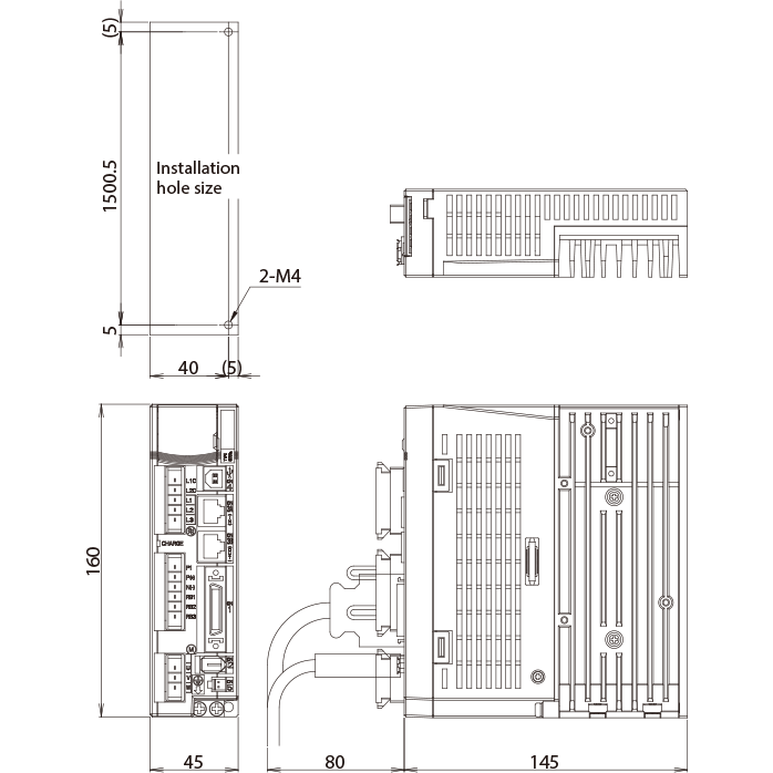
(Unit: mm) [Mass: 0.7kg]
Frame 2
| Power supply | Rated speed | Applicable motor output | Type |
|---|---|---|---|
| 100V series | 3000r/min | 0.2kW | RYT201D5-VE6 |
| 200V series | 0.4kW | RYT401D5-VE2 |
(Unit: mm) [Mass: 0.9kg]
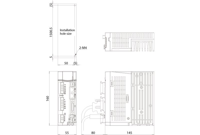
Frame 3
| Power supply | Rated speed | Applicable motor output | Type |
|---|---|---|---|
| 100V series | 3000r/min | 0.375kW | RYT401D5-VE6 |
| 200V series | 1500r/min | 0.5kW | RYT501B5-VE2 |
| 2000r/min | 0.5kW | RYT501C5-VE2 | |
| 0.75kW | RYT751C5-VE2 | ||
| 3000r/min | 0.75kW | RYT751D5-VE2 |
(Unit: mm) [Mass: 1.3kg]
Frame 4
| Rated speed | Applicable motor output | Type |
|---|---|---|
| 1500r/min | 0.85kW | RYT851B5-VE2 |
| 2000r/min | 1.0kW | RYT102C5-VE2 |
| 3000r/min | 1.0kW | RYT102D5-VE2 |
| 1.5kW | RYT152D5-VE2 |
(Unit: mm) [Mass: 1.4kg]
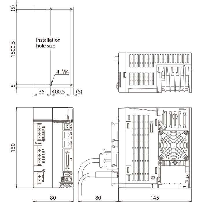
Frame 5
| Rated speed | Applicable motor output | Type | Mass |
|---|---|---|---|
| 1500r/min | 1.3kW | RYT13285-VE2 | 2.9kg |
| 2000r/min | 1.5kW | RYT152C5-VE2 | |
| 2.0kW | RYT202C5-VE2 | ||
| 3000r/min | 2.0kW | RYT202D5-VE2 | 2.6kg |
| 3.0kW | RYT302D5-VE2 |
(Unit: mm)
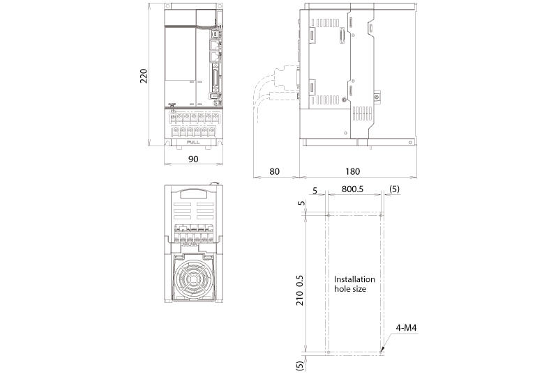
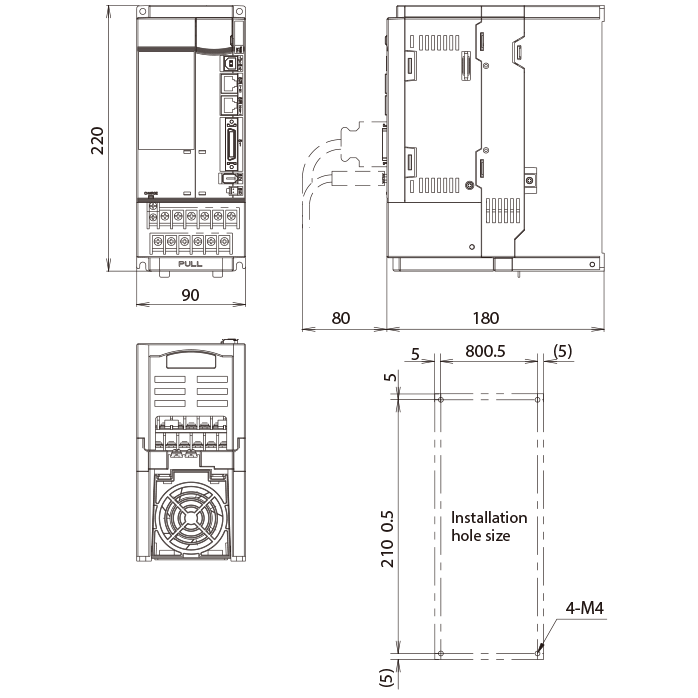
Frame 6
| Rated speed | Applicable motor output | Type |
|---|---|---|
| 3000r/min | 4.0kW | RYT402D5-VE2 |
| 5.0kW | RYT502D5-VE2 |
(Unit: mm) [Mass: 3.8kg]
Connection Diagram for Reference
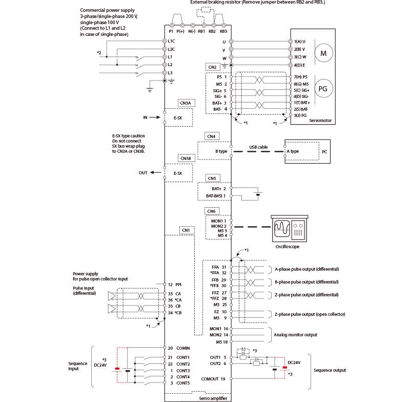
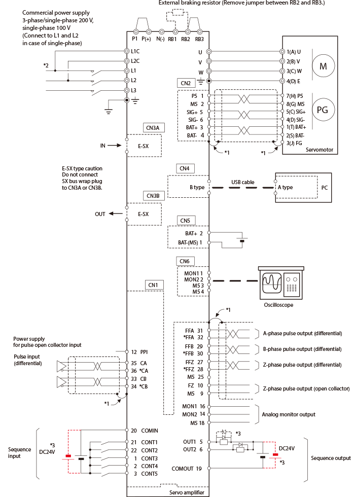
- *1:Connect the shield to the connector shell of CN1 and CN2. The connector shell is at the ground potential (FG).
- *2:Power must be supplied for the control power (L1c and L2c). (The servo amplifier will not function with only the main power supply.)
- *3:To use with the source I/O, connect as shown with the broken line. Connect the surge absorber diode for the output load with polarity reversed.
 Caution
The diagram shown above is given as a reference for model selection.
When actually using the selected servo system, make wiring connections according to the connection diagram and instructions described in the user's manual.
 Request catalog, purchase product
Please use this form to contact us about prices and delivery dates and to request catalogs.
Inquiry form Technical information inquiries
We accept pre-purchase technical inquiries about products by telephone, fax and email.
Inquiry form After-sales services
Please contact our nearest office about any issues with a product.