Specifications
-
Lineup in Japan
-
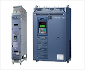
FRENIC-VG
-
Product information
- Unit Type, Stack Type, Converters
- Comprehensive Line-up
- Improved Control Performance
- A Wide Range of Applications
- Easier Maintenance
- Easier Maintenance and Greater Reliability
- Adaptation to Environment and Safety
- How to expand the capacity range of the inverters (Stack Type)
- How to expand the capacity range of the PWM converters (Stack Type)
- Variation
- Applicable SiC Hybrid Module Model
- Specifications
- External Dimensions
-
Catalog Download
- Document Download
-
Product information
- FRENIC-MEGA (G2)
-
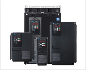
FRENIC-MEGA (G1)
-
Product information
- Best vector control for the general-purpose inverter in the class
- Accommodating various applications
- Wide model variation meeting the customer needs
- Supports for simple maintenance
- Network building
- Prolonged service life and improved life judgment function
- Consideration for environment
- Global compatibility
- Function Safety
- Variation
- Specifications
- External Dimensions
-
Catalog Download
- Document Download
-
Product information
-
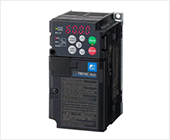
FRENIC-Ace (E3)
- Product information
- Variation
- Specifications
- External Dimensions
-
Catalog Download
- Document Download
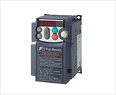
- FRENIC-Ace (E2)
- FRENIC-Mini
-
FRENIC-HVAC
- Product information
- Variation
- Specifications
- External Dimensions
-
Catalog Download
- Document Download
-
FRENIC-Eco
-
Product information
- Product appearance
- Exploded view of main body
- Keypad switches and functions
- Monitor display & key operation
- New energy-saving
- Long life design of inverters
- Simplified maintenance
- Optimum functions for HVAC
- Environment and panel design
- Operator-friendly features
- Network compatibility
- Global compatibility
- Variation
- Specifications
- External Dimensions
-
Catalog Download
- Document Download
-
Product information
-
FRENIC-Lift(LM1S)
- Product information
- Variation
- Specifications
- External Dimensions
-
Catalog Download
- Document Download
-
FRENIC-eRHR
- Product information
- Variation
- Specifications
- External Dimensions
-
Catalog Download
- Document Download
-
FRENIC-eRHC
- Product information
- Variation
- Specifications
- External Dimensions
-
Catalog Download
- Document Download
-
FRENIC-VG
-
Lineup in Europe
-
FRENIC-VG
-
Product information
- Unit Type, Stack Type, Converters
- Comprehensive Line-up
- Improved Control Performance
- A Wide Range of Applications
- Easier Maintenance
- Easier Maintenance and Greater Reliability
- Adaptation to Environment and Safety
- How to expand the capacity range of the inverters (Stack Type)
- How to expand the capacity range of the PWM converters (Stack Type)
- Variation
- Applicable SiC Hybrid Module Model
- Specifications
- External Dimensions
-
Catalog Download
- Document Download
-
Product information
- FRENIC-MEGA (G2)
-
FRENIC-MEGA (G1)
-
Product information
- Best vector control for the general-purpose inverter in the class
- Accommodating various applications
- Wide model variation meeting the customer needs
- Supports for simple maintenance
- Network building
- Prolonged service life and improved life judgment function
- Consideration for environment
- Global compatibility
- Function Safety
- Variation
- Specifications
- External Dimensions
-
Catalog Download
-
Product information
-
FRENIC-Ace (E3)
- Product information
- Variation
- Specifications
- External Dimensions
-
Catalog Download
- Document Download
- FRENIC-Ace (E2)
- FRENIC-Mini
- FVR-Micro
-
FRENIC-HVAC
- Product information
- Variation
- Specifications
- External Dimensions
-
Catalog Download
- Document Download
-
FRENIC-Eco
-
Product information
- Product appearance
- Exploded view of main body
- Keypad switches and functions
- Monitor display & key operation
- New energy-saving
- Long life design of inverters
- Simplified maintenance
- Optimum functions for HVAC
- Environment and panel design
- Operator-friendly features
- Network compatibility
- Global compatibility
- Variation
- Specifications
- External Dimensions
-
Catalog Download
- Document Download
-
Product information
- FRENIC-AQUA
-
FRENIC-Lift(LM1S)
- Product information
- Variation
- Specifications
- External Dimensions
-
Catalog Download
- Document Download
-
FRENIC-Lift(LM2A)
- Product information
- Variation
- Specifications
- External Dimensions
-
Catalog Download
- Document Download
-
FRENIC-eRHR
- Product information
- Variation
- Specifications
- External Dimensions
-
Catalog Download
- Document Download
-
FRENIC-eRHC
- Product information
- Variation
- Specifications
- External Dimensions
-
Catalog Download
- Document Download
-
FRENIC-VG
-
Lineup in North America
-
FRENIC-VG
-
Product information
- Unit Type, Stack Type, Converters
- Comprehensive Line-up
- Improved Control Performance
- A Wide Range of Applications
- Easier Maintenance
- Easier Maintenance and Greater Reliability
- Adaptation to Environment and Safety
- How to expand the capacity range of the inverters (Stack Type)
- How to expand the capacity range of the PWM converters (Stack Type)
- Variation
- Applicable SiC Hybrid Module Model
- Specifications
- External Dimensions
-
Catalog Download
- Document Download
-
Product information
- FRENIC-MEGA (G2)
-
FRENIC-MEGA (G1)
-
Product information
- Best vector control for the general-purpose inverter in the class
- Accommodating various applications
- Wide model variation meeting the customer needs
- Supports for simple maintenance
- Network building
- Prolonged service life and improved life judgment function
- Consideration for environment
- Global compatibility
- Function Safety
- Variation
- Specifications
- External Dimensions
-
Catalog Download
-
Product information
-
FRENIC-Ace (E3)
- Product information
- Variation
- Specifications
- External Dimensions
-
Catalog Download
- Document Download
- FRENIC-Ace (E2)
- FRENIC-Mini
-
FRENIC-HVAC
- Product information
- Variation
- Specifications
- External Dimensions
-
Catalog Download
- Document Download
-
FRENIC-Eco
-
Product information
- Product appearance
- Exploded view of main body
- Keypad switches and functions
- Monitor display & key operation
- New energy-saving
- Long life design of inverters
- Simplified maintenance
- Optimum functions for HVAC
- Environment and panel design
- Operator-friendly features
- Network compatibility
- Global compatibility
- Variation
- Specifications
- External Dimensions
-
Catalog Download
-
Product information
-
FRENIC-eRHR
- Product information
- Variation
- Specifications
- External Dimensions
-
Catalog Download
- Document Download
-
FRENIC-eRHC
- Product information
- Variation
- Specifications
- External Dimensions
-
Catalog Download
- Document Download
-
FRENIC-VG
-
Lineup in China
-
FRENIC-VG
-
Product information
- Unit Type, Stack Type, Converters
- Comprehensive Line-up
- Improved Control Performance
- A Wide Range of Applications
- Easier Maintenance
- Easier Maintenance and Greater Reliability
- Adaptation to Environment and Safety
- How to expand the capacity range of the inverters (Stack Type)
- How to expand the capacity range of the PWM converters (Stack Type)
- Variation
- Applicable SiC Hybrid Module Model
- Specifications
- External Dimensions
-
Catalog Download
- Document Download
-
Product information
- FRENIC-MEGA (G2)
-
FRENIC-MEGA (G1)
-
Product information
- Best vector control for the general-purpose inverter in the class
- Accommodating various applications
- Wide model variation meeting the customer needs
- Supports for simple maintenance
- Network building
- Prolonged service life and improved life judgment function
- Consideration for environment
- Global compatibility
- Function Safety
- Variation
- Specifications
- External Dimensions
-
Catalog Download
- Document Download
-
Product information
-
FRENIC-Ace (E3)
- Product information
- Variation
- Specifications
- External Dimensions
-
Catalog Download
- Document Download
- FRENIC-Ace (E2)
- FRENIC-Mini
- FVR-Micro
-
FRENIC VP
- Product information
- Variation
- Specifications
- External Dimensions
-
Catalog Download
-
For Europe
- For China
-
- Document Download
- FRENIC-Lift(LM1S)
- FRENIC-eRHR
-
FRENIC-eRHC
- Product information
- Variation
- Specifications
- External Dimensions
-
Catalog Download
- Document Download
-
FRENIC-VG
-
Lineup in Asia
-
FRENIC-VG
-
Product information
- Unit Type, Stack Type, Converters
- Comprehensive Line-up
- Improved Control Performance
- A Wide Range of Applications
- Easier Maintenance
- Easier Maintenance and Greater Reliability
- Adaptation to Environment and Safety
- How to expand the capacity range of the inverters (Stack Type)
- How to expand the capacity range of the PWM converters (Stack Type)
- Variation
- Applicable SiC Hybrid Module Model
- Specifications
- External Dimensions
-
Catalog Download
- Document Download
-
Product information
- FRENIC-MEGA (G2)
-
FRENIC-MEGA (G1)
-
Product information
- Best vector control for the general-purpose inverter in the class
- Accommodating various applications
- Wide model variation meeting the customer needs
- Supports for simple maintenance
- Network building
- Prolonged service life and improved life judgment function
- Consideration for environment
- Global compatibility
- Function Safety
- Variation
- Specifications
- External Dimensions
-
Catalog Download
- Document Download
-
Product information
-
FRENIC-Ace (E3)
- Product information
- Variation
- Specifications
- External Dimensions
-
Catalog Download
- Document Download
- FRENIC-Ace (E2)
- FRENIC-Mini
- FVR-Micro
-
FRENIC-HVAC
- Product information
- Variation
- Specifications
- External Dimensions
-
Catalog Download
- Document Download
-
FRENIC-Eco
-
Product information
- Product appearance
- Exploded view of main body
- Keypad switches and functions
- Monitor display & key operation
- New energy-saving
- Long life design of inverters
- Simplified maintenance
- Optimum functions for HVAC
- Environment and panel design
- Operator-friendly features
- Network compatibility
- Global compatibility
- Variation
- Specifications
- External Dimensions
-
Catalog Download
- Document Download
-
Product information
- FRENIC-AQUA
- FRENIC eHVAC
-
FRENIC-Lift(LM1S)
- Product information
- Variation
- Specifications
- External Dimensions
-
Catalog Download
- Document Download
-
FRENIC-eRHR
- Product information
- Variation
- Specifications
- External Dimensions
-
Catalog Download
- Document Download
-
FRENIC-eRHC
- Product information
- Variation
- Specifications
- External Dimensions
-
Catalog Download
- Document Download
-
FRENIC-VG
-
Lineup in Taiwan
-
FRENIC-VG
-
Product information
- Unit Type, Stack Type, Converters
- Comprehensive Line-up
- Improved Control Performance
- A Wide Range of Applications
- Easier Maintenance
- Easier Maintenance and Greater Reliability
- Adaptation to Environment and Safety
- How to expand the capacity range of the inverters (Stack Type)
- How to expand the capacity range of the PWM converters (Stack Type)
- Variation
- Applicable SiC Hybrid Module Model
- Specifications
- External Dimensions
-
Catalog Download
- Document Download
-
Product information
- FRENIC-MEGA (G2)
-
FRENIC-MEGA (G1)
-
Product information
- Best vector control for the general-purpose inverter in the class
- Accommodating various applications
- Wide model variation meeting the customer needs
- Supports for simple maintenance
- Network building
- Prolonged service life and improved life judgment function
- Consideration for environment
- Global compatibility
- Function Safety
- Variation
- Specifications
- External Dimensions
-
Catalog Download
- Document Download
-
Product information
-
FRENIC-Ace (E3)
- Product information
- Variation
- Specifications
- External Dimensions
-
Catalog Download
- Document Download
- FRENIC-Ace (E2)
-
FRENIC-Eco
-
Product information
- Product appearance
- Exploded view of main body
- Keypad switches and functions
- Monitor display & key operation
- New energy-saving
- Long life design of inverters
- Simplified maintenance
- Optimum functions for HVAC
- Environment and panel design
- Operator-friendly features
- Network compatibility
- Global compatibility
- Variation
- Specifications
- External Dimensions
-
Catalog Download
- Document Download
-
Product information
-
FRENIC-Lift(LM1S)
- Product information
- Variation
- Specifications
- External Dimensions
-
Catalog Download
- Document Download
-
FRENIC-eRHR
- Product information
- Variation
- Specifications
- External Dimensions
-
Catalog Download
- Document Download
-
FRENIC-eRHC
- Product information
- Variation
- Specifications
- External Dimensions
-
Catalog Download
- Document Download
-
FRENIC-VG
-
Lineup in Korea
-
FRENIC-VG
-
Product information
- Unit Type, Stack Type, Converters
- Comprehensive Line-up
- Improved Control Performance
- A Wide Range of Applications
- Easier Maintenance
- Easier Maintenance and Greater Reliability
- Adaptation to Environment and Safety
- How to expand the capacity range of the inverters (Stack Type)
- How to expand the capacity range of the PWM converters (Stack Type)
- Variation
- Applicable SiC Hybrid Module Model
- Specifications
- External Dimensions
-
Catalog Download
- Document Download
-
Product information
- FRENIC-MEGA (G2)
-
FRENIC-MEGA (G1)
-
Product information
- Best vector control for the general-purpose inverter in the class
- Accommodating various applications
- Wide model variation meeting the customer needs
- Supports for simple maintenance
- Network building
- Prolonged service life and improved life judgment function
- Consideration for environment
- Global compatibility
- Function Safety
- Variation
- Specifications
- External Dimensions
-
Catalog Download
- Document Download
-
Product information
-
FRENIC-Ace (E3)
- Product information
- Variation
- Specifications
- External Dimensions
-
Catalog Download
- Document Download
- FRENIC-Ace (E2)
- FRENIC-Mini
- FRENIC-Eco
-
FRENIC-Lift(LM1S)
- Product information
- Variation
- Specifications
- External Dimensions
-
Catalog Download
- Document Download
-
FRENIC-eRHR
- Product information
- Variation
- Specifications
- External Dimensions
-
Catalog Download
- Document Download
-
FRENIC-eRHC
- Product information
- Variation
- Specifications
- External Dimensions
-
Catalog Download
- Document Download
-
FRENIC-VG

-
*1
-
Fuji 4-pole standard motor
-
*2
-
Rated capacity is calculated by assuming the output rated voltage as 220V for three-phase 200V series.
-
*3
-
Output voltage cannot exceed the power supply voltage.
-
*4
-
An excessively low setting of the carrier frequency may result in the higher motor temperature or tripping of the inverter by its overcurrent limiter setting. Lower the continuous load or maximum load instead. (When setting the carrier frequency (F26) to 1kHz, reduce the load to 80% of its rating.)
-
*5
-
Trial calculation done on assumption that the power capacity is 500kVA (or 10 times the inverter capacity if the inverter capacity is larger than 50kVA) and the inverter is connected to the power supply of %X=5%.
-
*6
-
Obtained when a DC reactor (DCR) is used.
-
*7
-
Average braking torque (Varies with the efficiency of the motor.)
-
*8
-
Voltage unbalance (%) = ( MAX. voltage(V) - Min. voltage(V) ) / ( Three-phase average voltage(V) ) x 67 (IEC61800-3 (5.2.3))
If this value is 2 to 3%, use an AC reactor (ACR option).
-
*9
-
Use [R1, T1] terminals for driving AC cooling fans of an inverter powered by the DC link bus, such as by a high power factor PWM converter. (In ordinary operation, the terminals are not used.)
-
*10
-
When using the inverter at an ambient temperature higher than 40°C and at a carrier frequency of 3kHz or over, select the inverter so that the current does not exceed the rated current specified in ( ) during continuous operation.


-
*1
-
Fuji 4-pole standard motor
-
*2
-
Rated capacity is calculated by assuming the output rated voltage as 440V for three-phase 400 V series.
-
*3
-
Output voltage cannot exceed the power supply voltage.
-
*4
-
An excessively low setting of the carrier frequency may result in the higher motor temperature or tripping of the inverter by its overcurrent limiter setting. Lower the continuous load or maximum load instead. (When setting the carrier frequency (F26) to 1kHz, reduce the load to 80% of its rating.)
-
*5
-
Trial calculation done on assumption that the power capacity is 500kVA (or 10 times the inverter capacity if the inverter capacity is larger than 50kVA) and the inverter is connected to the power supply of %X=5%.
-
*6
-
Obtained when a DC reactor (DCR) is used.
-
*7
-
Average braking torque (Varies with the efficiency of the motor.)
-
*8
-
Voltage unbalance (%) = ( MAX. voltage(V) - Min. voltage(V) ) / ( Three-phase average voltage(V) ) x 67 (IEC61800-3) If this value is 2 to 3%, use an AC reactor (ACR option).
-
*9
-
Use [R1, T1] terminals for driving AC cooling fans of an inverter powered by the DC link bus, such as by a high power factor PWM converter. (In ordinary operation, the terminals are not used.)

-
*1
-
Standard 4-pole motor
-
*2
-
Rated capacity is calculated by assuming the output rated voltage as 208V for three-phase 208V.
-
*3
-
Output voltage cannot exceed the power supply voltage.
-
*4
-
An excessively low setting of the carrier frequency may result in the higher motor temperature or tripping of the inverter by its overcurrent limiter setting. Lower the continuous load or maximum load instead. (When setting the carrier frequency (F26) to 1kHz, reduce the load to 80% of its rating.)
-
*5
-
Use [R1,T1] terminals for driving AC cooling fans of an inverter powered by the DC link bus, such as by a high power factor PWM converter. (In ordinary operation, the terminals are not used.)
-
*6
-
Calculated under Fuji-specified conditions.
-
*7
-
Obtained when a DC reactor (DCR) is used.
-
*8
-
Average braking torque (Varies with the efficiency of the motor.)
-
*9
-
Voltage unbalance (%) = ( ( MAX. voltage(V) - Min. voltage(V) ) / Three-phase average voltage(V) ) x 67 (IEC61800-3 (5.2.3))
If this value is 2 to 3%, use an AC reactor (ACR).


-
*1
-
Standard 4-pole motor
-
*2
-
Rated capacity is calculated by assuming the output rated voltage as 460V for three-phase 460V.
-
*3
-
Output voltage cannot exceed the power supply voltage.
-
*4
-
An excessively low setting of the carrier frequency may result in the higher motor temperature or tripping of the inverter by its overcurrent limiter setting. Lower the continuous load or maximum load instead. (When setting the carrier frequency (F26) to 1kHz, reduce the load to 80% of its rating.)
-
*5
-
Use [R1,T1] terminals for driving AC cooling fans of an inverter powered by the DC link bus, such as by a high power factor PWM converter. (In ordinary operation, the terminals are not used.)
-
*6
-
Calculated under Fuji-specified conditions.
-
*7
-
Obtained when a DC reactor (DCR) is used.
-
*8
-
Average braking torque (Varies with the efficiency of the motor.)
-
*9
-
Voltage unbalance (%) = ( ( MAX. voltage(V) - Min. voltage(V) ) / Three-phase average voltage(V) ) x 67 (IEC61800-3 (5.2.3))
If this value is 2 to 3%, use an AC reactor (ACR).

-
*1
-
Fuji 4-pole standard motor
-
*2
-
Rated capacity is calculated by assuming the output rated voltage as 220V for three-phase 200V series.
-
*3
-
Output voltage cannot exceed the power supply voltage.
-
*4
-
An excessively low setting of the carrier frequency may result in the higher motor temperature or tripping of the inverter by its overcurrent limiter setting. Lower the continuous load or maximum load instead. (When setting the carrier frequency (F26) to 1kHz, reduce the load to 80% of its rating.)
-
*5
-
Trial calculation done on assumption that the power capacity is 500kVA (or 10 times the inverter capacity if the inverter capacity is larger than 50kVA) and the inverter is connected to the power supply of %X=5%.
-
*6
-
Obtained when a DC reactor (DCR) is used.
-
*7
-
Average braking torque (Varies with the efficiency of the motor.)
-
*8
-
Voltage unbalance (%) = ( MAX. voltage(V) - Min. voltage(V) ) / ( Three-phase average voltage(V) ) x 67 (IEC61800-3 (5.2.3))
If this value is 2 to 3%, use an AC reactor (ACR option).
-
*9
-
Use [R1, T1] terminals for driving AC cooling fans of an inverter powered by the DC link bus, such as by a high power factor PWM converter. (In ordinary operation, the terminals are not used.)
-
*10
-
When using the inverter at an ambient temperature higher than 40°C and at a carrier frequency of 3kHz or over, select the inverter so that the current does not exceed the rated current specified in ( ) during continuous operation.


-
*1
-
Fuji 4-pole standard motor
-
*2
-
Rated capacity is calculated by assuming the output rated voltage as 440V for three-phase 400 V series.
-
*3
-
Output voltage cannot exceed the power supply voltage.
-
*4
-
An excessively low setting of the carrier frequency may result in the higher motor temperature or tripping of the inverter by its overcurrent limiter setting. Lower the continuous load or maximum load instead. (When setting the carrier frequency (F26) to 1kHz, reduce the load to 80% of its rating.)
-
*5
-
Trial calculation done on assumption that the power capacity is 500kVA (or 10 times the inverter capacity if the inverter capacity is larger than 50kVA) and the inverter is connected to the power supply of %X=5%.
-
*6
-
Obtained when a DC reactor (DCR) is used.
-
*7
-
Average braking torque (Varies with the efficiency of the motor.)
-
*8
-
Voltage unbalance (%) = ( MAX. voltage(V) - Min. voltage(V) ) / ( Three-phase average voltage(V) ) x 67 (IEC61800-3) If this value is 2 to 3%, use an AC reactor (ACR option).
-
*9
-
Use [R1, T1] terminals for driving AC cooling fans of an inverter powered by the DC link bus, such as by a high power factor PWM converter. (In ordinary operation, the terminals are not used.)