Product information
-
Lineup in Japan
-
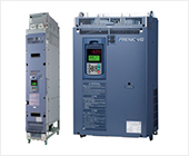
FRENIC-VG
-
Product information
- Unit Type, Stack Type, Converters
- Comprehensive Line-up
- Improved Control Performance
- A Wide Range of Applications
- Easier Maintenance
- Easier Maintenance and Greater Reliability
- Adaptation to Environment and Safety
- How to expand the capacity range of the inverters (Stack Type)
- How to expand the capacity range of the PWM converters (Stack Type)
- Variation
- Applicable SiC Hybrid Module Model
- Specifications
- External Dimensions
-
Catalog Download
- Document Download
-
Product information
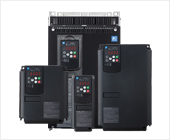
- FRENIC-MEGA (G2)
-
FRENIC-MEGA (G1)
-
Product information
- Best vector control for the general-purpose inverter in the class
- Accommodating various applications
- Wide model variation meeting the customer needs
- Supports for simple maintenance
- Network building
- Prolonged service life and improved life judgment function
- Consideration for environment
- Global compatibility
- Function Safety
- Variation
- Specifications
- External Dimensions
-
Catalog Download
- Document Download
-
Product information
-
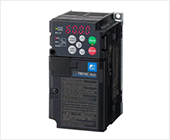
FRENIC-Ace (E3)
- Product information
- Variation
- Specifications
- External Dimensions
-
Catalog Download
- Document Download
- FRENIC-Ace (E2)
- FRENIC-Mini
-
FRENIC-HVAC
- Product information
- Variation
- Specifications
- External Dimensions
-
Catalog Download
- Document Download
-
FRENIC-Eco
-
Product information
- Product appearance
- Exploded view of main body
- Keypad switches and functions
- Monitor display & key operation
- New energy-saving
- Long life design of inverters
- Simplified maintenance
- Optimum functions for HVAC
- Environment and panel design
- Operator-friendly features
- Network compatibility
- Global compatibility
- Variation
- Specifications
- External Dimensions
-
Catalog Download
- Document Download
-
Product information
-
FRENIC-Lift(LM1S)
- Product information
- Variation
- Specifications
- External Dimensions
-
Catalog Download
- Document Download
-
FRENIC-eRHR
- Product information
- Variation
- Specifications
- External Dimensions
-
Catalog Download
- Document Download
-
FRENIC-eRHC
- Product information
- Variation
- Specifications
- External Dimensions
-
Catalog Download
- Document Download
-
FRENIC-VG
-
Lineup in Europe
-
FRENIC-VG
-
Product information
- Unit Type, Stack Type, Converters
- Comprehensive Line-up
- Improved Control Performance
- A Wide Range of Applications
- Easier Maintenance
- Easier Maintenance and Greater Reliability
- Adaptation to Environment and Safety
- How to expand the capacity range of the inverters (Stack Type)
- How to expand the capacity range of the PWM converters (Stack Type)
- Variation
- Applicable SiC Hybrid Module Model
- Specifications
- External Dimensions
-
Catalog Download
- Document Download
-
Product information
- FRENIC-MEGA (G2)
-
FRENIC-MEGA (G1)
-
Product information
- Best vector control for the general-purpose inverter in the class
- Accommodating various applications
- Wide model variation meeting the customer needs
- Supports for simple maintenance
- Network building
- Prolonged service life and improved life judgment function
- Consideration for environment
- Global compatibility
- Function Safety
- Variation
- Specifications
- External Dimensions
-
Catalog Download
-
Product information
-
FRENIC-Ace (E3)
- Product information
- Variation
- Specifications
- External Dimensions
-
Catalog Download
- Document Download
- FRENIC-Ace (E2)
- FRENIC-Mini
- FVR-Micro
-
FRENIC-HVAC
- Product information
- Variation
- Specifications
- External Dimensions
-
Catalog Download
- Document Download
-
FRENIC-Eco
-
Product information
- Product appearance
- Exploded view of main body
- Keypad switches and functions
- Monitor display & key operation
- New energy-saving
- Long life design of inverters
- Simplified maintenance
- Optimum functions for HVAC
- Environment and panel design
- Operator-friendly features
- Network compatibility
- Global compatibility
- Variation
- Specifications
- External Dimensions
-
Catalog Download
- Document Download
-
Product information
- FRENIC-AQUA
-
FRENIC-Lift(LM1S)
- Product information
- Variation
- Specifications
- External Dimensions
-
Catalog Download
- Document Download
-
FRENIC-Lift(LM2A)
- Product information
- Variation
- Specifications
- External Dimensions
-
Catalog Download
- Document Download
-
FRENIC-eRHR
- Product information
- Variation
- Specifications
- External Dimensions
-
Catalog Download
- Document Download
-
FRENIC-eRHC
- Product information
- Variation
- Specifications
- External Dimensions
-
Catalog Download
- Document Download
-
FRENIC-VG
-
Lineup in North America
-
FRENIC-VG
-
Product information
- Unit Type, Stack Type, Converters
- Comprehensive Line-up
- Improved Control Performance
- A Wide Range of Applications
- Easier Maintenance
- Easier Maintenance and Greater Reliability
- Adaptation to Environment and Safety
- How to expand the capacity range of the inverters (Stack Type)
- How to expand the capacity range of the PWM converters (Stack Type)
- Variation
- Applicable SiC Hybrid Module Model
- Specifications
- External Dimensions
-
Catalog Download
- Document Download
-
Product information
- FRENIC-MEGA (G2)
-
FRENIC-MEGA (G1)
-
Product information
- Best vector control for the general-purpose inverter in the class
- Accommodating various applications
- Wide model variation meeting the customer needs
- Supports for simple maintenance
- Network building
- Prolonged service life and improved life judgment function
- Consideration for environment
- Global compatibility
- Function Safety
- Variation
- Specifications
- External Dimensions
-
Catalog Download
-
Product information
-
FRENIC-Ace (E3)
- Product information
- Variation
- Specifications
- External Dimensions
-
Catalog Download
- Document Download
- FRENIC-Ace (E2)
- FRENIC-Mini
-
FRENIC-HVAC
- Product information
- Variation
- Specifications
- External Dimensions
-
Catalog Download
- Document Download
-
FRENIC-Eco
-
Product information
- Product appearance
- Exploded view of main body
- Keypad switches and functions
- Monitor display & key operation
- New energy-saving
- Long life design of inverters
- Simplified maintenance
- Optimum functions for HVAC
- Environment and panel design
- Operator-friendly features
- Network compatibility
- Global compatibility
- Variation
- Specifications
- External Dimensions
-
Catalog Download
-
Product information
-
FRENIC-eRHR
- Product information
- Variation
- Specifications
- External Dimensions
-
Catalog Download
- Document Download
-
FRENIC-eRHC
- Product information
- Variation
- Specifications
- External Dimensions
-
Catalog Download
- Document Download
-
FRENIC-VG
-
Lineup in China
-
FRENIC-VG
-
Product information
- Unit Type, Stack Type, Converters
- Comprehensive Line-up
- Improved Control Performance
- A Wide Range of Applications
- Easier Maintenance
- Easier Maintenance and Greater Reliability
- Adaptation to Environment and Safety
- How to expand the capacity range of the inverters (Stack Type)
- How to expand the capacity range of the PWM converters (Stack Type)
- Variation
- Applicable SiC Hybrid Module Model
- Specifications
- External Dimensions
-
Catalog Download
- Document Download
-
Product information
- FRENIC-MEGA (G2)
-
FRENIC-MEGA (G1)
-
Product information
- Best vector control for the general-purpose inverter in the class
- Accommodating various applications
- Wide model variation meeting the customer needs
- Supports for simple maintenance
- Network building
- Prolonged service life and improved life judgment function
- Consideration for environment
- Global compatibility
- Function Safety
- Variation
- Specifications
- External Dimensions
-
Catalog Download
- Document Download
-
Product information
-
FRENIC-Ace (E3)
- Product information
- Variation
- Specifications
- External Dimensions
-
Catalog Download
- Document Download
- FRENIC-Ace (E2)
- FRENIC-Mini
- FVR-Micro
-
FRENIC VP
- Product information
- Variation
- Specifications
- External Dimensions
-
Catalog Download
-
For Europe
- For China
-
- Document Download
- FRENIC-Lift(LM1S)
- FRENIC-eRHR
-
FRENIC-eRHC
- Product information
- Variation
- Specifications
- External Dimensions
-
Catalog Download
- Document Download
-
FRENIC-VG
-
Lineup in Asia
-
FRENIC-VG
-
Product information
- Unit Type, Stack Type, Converters
- Comprehensive Line-up
- Improved Control Performance
- A Wide Range of Applications
- Easier Maintenance
- Easier Maintenance and Greater Reliability
- Adaptation to Environment and Safety
- How to expand the capacity range of the inverters (Stack Type)
- How to expand the capacity range of the PWM converters (Stack Type)
- Variation
- Applicable SiC Hybrid Module Model
- Specifications
- External Dimensions
-
Catalog Download
- Document Download
-
Product information
- FRENIC-MEGA (G2)
-
FRENIC-MEGA (G1)
-
Product information
- Best vector control for the general-purpose inverter in the class
- Accommodating various applications
- Wide model variation meeting the customer needs
- Supports for simple maintenance
- Network building
- Prolonged service life and improved life judgment function
- Consideration for environment
- Global compatibility
- Function Safety
- Variation
- Specifications
- External Dimensions
-
Catalog Download
- Document Download
-
Product information
-
FRENIC-Ace (E3)
- Product information
- Variation
- Specifications
- External Dimensions
-
Catalog Download
- Document Download
- FRENIC-Ace (E2)
- FRENIC-Mini
- FVR-Micro
-
FRENIC-HVAC
- Product information
- Variation
- Specifications
- External Dimensions
-
Catalog Download
- Document Download
-
FRENIC-Eco
-
Product information
- Product appearance
- Exploded view of main body
- Keypad switches and functions
- Monitor display & key operation
- New energy-saving
- Long life design of inverters
- Simplified maintenance
- Optimum functions for HVAC
- Environment and panel design
- Operator-friendly features
- Network compatibility
- Global compatibility
- Variation
- Specifications
- External Dimensions
-
Catalog Download
- Document Download
-
Product information
- FRENIC-AQUA
- FRENIC eHVAC
-
FRENIC-Lift(LM1S)
- Product information
- Variation
- Specifications
- External Dimensions
-
Catalog Download
- Document Download
-
FRENIC-eRHR
- Product information
- Variation
- Specifications
- External Dimensions
-
Catalog Download
- Document Download
-
FRENIC-eRHC
- Product information
- Variation
- Specifications
- External Dimensions
-
Catalog Download
- Document Download
-
FRENIC-VG
-
Lineup in Taiwan
-
FRENIC-VG
-
Product information
- Unit Type, Stack Type, Converters
- Comprehensive Line-up
- Improved Control Performance
- A Wide Range of Applications
- Easier Maintenance
- Easier Maintenance and Greater Reliability
- Adaptation to Environment and Safety
- How to expand the capacity range of the inverters (Stack Type)
- How to expand the capacity range of the PWM converters (Stack Type)
- Variation
- Applicable SiC Hybrid Module Model
- Specifications
- External Dimensions
-
Catalog Download
- Document Download
-
Product information
- FRENIC-MEGA (G2)
-
FRENIC-MEGA (G1)
-
Product information
- Best vector control for the general-purpose inverter in the class
- Accommodating various applications
- Wide model variation meeting the customer needs
- Supports for simple maintenance
- Network building
- Prolonged service life and improved life judgment function
- Consideration for environment
- Global compatibility
- Function Safety
- Variation
- Specifications
- External Dimensions
-
Catalog Download
- Document Download
-
Product information
-
FRENIC-Ace (E3)
- Product information
- Variation
- Specifications
- External Dimensions
-
Catalog Download
- Document Download
- FRENIC-Ace (E2)
-
FRENIC-Eco
-
Product information
- Product appearance
- Exploded view of main body
- Keypad switches and functions
- Monitor display & key operation
- New energy-saving
- Long life design of inverters
- Simplified maintenance
- Optimum functions for HVAC
- Environment and panel design
- Operator-friendly features
- Network compatibility
- Global compatibility
- Variation
- Specifications
- External Dimensions
-
Catalog Download
- Document Download
-
Product information
-
FRENIC-Lift(LM1S)
- Product information
- Variation
- Specifications
- External Dimensions
-
Catalog Download
- Document Download
-
FRENIC-eRHR
- Product information
- Variation
- Specifications
- External Dimensions
-
Catalog Download
- Document Download
-
FRENIC-eRHC
- Product information
- Variation
- Specifications
- External Dimensions
-
Catalog Download
- Document Download
-
FRENIC-VG
-
Lineup in Korea
-
FRENIC-VG
-
Product information
- Unit Type, Stack Type, Converters
- Comprehensive Line-up
- Improved Control Performance
- A Wide Range of Applications
- Easier Maintenance
- Easier Maintenance and Greater Reliability
- Adaptation to Environment and Safety
- How to expand the capacity range of the inverters (Stack Type)
- How to expand the capacity range of the PWM converters (Stack Type)
- Variation
- Applicable SiC Hybrid Module Model
- Specifications
- External Dimensions
-
Catalog Download
- Document Download
-
Product information
- FRENIC-MEGA (G2)
-
FRENIC-MEGA (G1)
-
Product information
- Best vector control for the general-purpose inverter in the class
- Accommodating various applications
- Wide model variation meeting the customer needs
- Supports for simple maintenance
- Network building
- Prolonged service life and improved life judgment function
- Consideration for environment
- Global compatibility
- Function Safety
- Variation
- Specifications
- External Dimensions
-
Catalog Download
- Document Download
-
Product information
-
FRENIC-Ace (E3)
- Product information
- Variation
- Specifications
- External Dimensions
-
Catalog Download
- Document Download
- FRENIC-Ace (E2)
- FRENIC-Mini
- FRENIC-Eco
-
FRENIC-Lift(LM1S)
- Product information
- Variation
- Specifications
- External Dimensions
-
Catalog Download
- Document Download
-
FRENIC-eRHR
- Product information
- Variation
- Specifications
- External Dimensions
-
Catalog Download
- Document Download
-
FRENIC-eRHC
- Product information
- Variation
- Specifications
- External Dimensions
-
Catalog Download
- Document Download
-
FRENIC-VG
The cascade control is the function that controls the multiple pumps by one inverter. The pumps are controlled with combination of inverter drive and commercial drive. This can be applied in a large-scale water treatment plant.
In cascade control, the signals of flow rate and pressure sensors are controlled by the PID regulator that is built in the inverter. Each pump is driven either by the inverter or commercially according to the switching signal from the inverter. The pumps are controlled only by the inverter when the discharge volume is small, and adding to the inverter drive, they are controlled using commercial drive by adding them one by one as the discharge volume gets larger in order to ensure the required discharge volume in total. There are two following methods in control: inverter drive motor fixed method and inverter drive motor fixed method.
The system is configured by combining the motor driven by the inverter (M0), motors that are commercially driven (M1 to M8) and auxiliary motor (MA). The motor driven by the inverter is always fixed as motor M0. Motors commercially driven are added one by one in control when the required discharge flow rate cannot be achieved with the motor M0 only.
The system for this method is configured by combining the motors that can be switched between inverter drive and commercial drive (M1 to M4) and auxiliary motor that are commercially driven (MA). The motors are driven by the inverter with variable speed control at start. When the desired discharge flow rate cannot be achieved with the first motor, operations FLOATING-1 or FLOATING-2 can be selected.

The first motor: Switched as a commercially driven motor
Second and subsequent motors: Operated by inverter drive
The inverter-driven motor is changed by rotation as the motor is added.
The first motor: Inverter drive continued
Second and subsequent motors: Commercially driven
The system can be configured without using a controller by connecting the inverters via communications. In this system, if a failure occurs to the master inverter, the next inverter is driven as the master inverter. Moreover, wiring can be saved with use of communications services, which eliminates the need of additional options by using the Modbus RTU communications.
The customized logic interface function is provided to the inverter body. This enables forming of logic circuit and arithmetic circuit to the digital and analog input and output signals, allowing simple relay sequence to be built while processing the signals freely.
Frequency can be output forcibly at a fixed rate in preference to PID control. By setting the operation frequency, operation time, and acceleration time at starting, optimal operation for starting the pump can be achieved.
-
Pressurizing operation can be applied for a certain period of time at the time of start.
Function codes can be read/write, displayed or hidden by setting the two passwords. This prevents erroneous operation or overwriting of function codes. In addition, if a wrong password was input exceeding the specified number of times, the inverter is restricted from operating as the user is regarded as improper.
Pump dry condition can be detected from PID deviation value by setting the output frequency, output current, and flow rate sensor value. Water leakage and pressure drop due to impeller damage can be detected as well.
The inverter can be stopped when the discharge rate becomes low due to increase of pump discharge pressure. Facility having a bladder tank can make the stoppage period longer by applying pressure immediately before stoppage, which realizes energy-saving operation.
When a pump such as a deep well pump is operated at low speed over a long period of time, the pump may be damaged since the load current is large in the low-speed range. It is possible to provide acceleration/deceleration time specific to the low-speed range in order to avoid prolonged operation.
The motor is rotated in reverse when it is determined that any abnormality, such as being engaged or trapped, is occurred. If sand or dust were caught in the impeller with a submerged pump and overcurrent protection function is activated, the motor is rotated in reverse at restart so that the sand and dust are ejected from the impeller. Then, the motor resumes rotation in forward, allowing water to be supplied in a normal manner.
-
4PID control
-
Control of maximum starts per hour
-
Abnormal pressure rise prevention
-
End of curve detection
-
Pick-up operation
If a valve is closed quickly after pump stoppage, there is a risk of damaging the check valve (piping, pump, valves, etc.) due to water hammer phenomenon. To protect the check valve from this, the pump speed is gradually slowed down when the check valve closes.